tomerbr
Junior Member level 2
Hi,
I am designing a system to control fan speeds.
The selection of the speeds will be done using an MCU that will select the correct output to the fan.
The selection is done by a single push button, each press changes the speed.
This logic is working using a push-button connected directly to the MCU and the 5V supply.
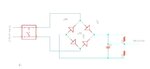
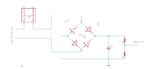
In the final system, the push button will send a ~230V AC pulse instead of a 5V DC pulses.
I need to interface this into my 5V MCU.
My idea is to use a diode bridge and a voltage devider like in the attched schematic.
Will it work?
Thanks,
Tomer
I am designing a system to control fan speeds.
The selection of the speeds will be done using an MCU that will select the correct output to the fan.
The selection is done by a single push button, each press changes the speed.
This logic is working using a push-button connected directly to the MCU and the 5V supply.
In the final system, the push button will send a ~230V AC pulse instead of a 5V DC pulses.
I need to interface this into my 5V MCU.
My idea is to use a diode bridge and a voltage devider like in the attched schematic.
Will it work?
Thanks,
Tomer