Continue to Site

Welcome to EDAboard.com

Welcome to our site! EDAboard.com is an international Electronics Discussion Forum focused on EDA software, circuits, schematics, books, theory, papers, asic, pld, 8051, DSP, Network, RF, Analog Design, PCB, Service Manuals... and a whole lot more! To participate you need to register. Registration is free. Click here to register now.

Calculation of Input and Output impedance for impedance matching of a half wave recti

Status
Not open for further replies.

ab_basu

Newbie level 5
Joined
Jun 21, 2019
Messages
9
Helped
0
Reputation
0
Reaction score
0
Trophy points
1
Activity points
92
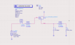
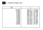
hi, I have recently started working on RF. I have designed a simple half wave rectifier circuit and did run the HB simulation. But now I want to do the impedance matching. But I am not sure how to match the impedance with 50 ohm souce pf P1_Tone. I have done Vin/I_probe1 for the Zin. But I dont know id the value is right or not.

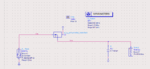
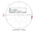
I have also done Sparameter simulation for impedance. But I got different value from S11. Which Zinput value is correct.

what Zin value should I use for impedance matching?

Please suggest which is the right way.

I am attaching my design. Please help me asap.
 

Attachments

  • 12.PNG
    12.PNG
    22.8 KB · Views: 189
  • 13.PNG
    13.PNG
    9.8 KB · Views: 182
  • 14.PNG
    14.PNG
    18.9 KB · Views: 191
  • 15.PNG
    15.PNG
    15.5 KB · Views: 179

Only a large signal analysis like HB can give correct results for a rectifier circuit.

Consider that exact impedance matching is only possible for a single input level and frequency. Also that most of the input power is reflected in your HB measurement, you need HB measurements with absorbed power level in the intended range.
 

You did it right so Large Signal Input Impedance is Vin/I_Probe.i @ Particular Input Power
You found an impedance table that varies by Pin_av that is normal then pick an impedance which is proper after that design your matching circuit regarding to this impedance.
S-parameter simulation is not convenient for that circuit because the nature of rectifiers is Nonlinear so it doesn't make sense to take s-parameters into account.
 

    jihen

    Points: 2
    Helpful Answer Positive Rating
Thank you for your replies, I really appreciate this.

So, basically my impedance calculation is correct? I mean the V/R formula for HB analysis?

now there are some doubts:

1. If I dont run the S-parameter simulation, how can I get S11(db) value?

2. I am using the formula P_Probe2[0]/dbmtow(Pin) for efficiency. Is it correct?

3. Next, what procedure should I follow for impedance matching? Smith chart utility?

4. I dint understand the comment 'HB measurements with absorbed power level in the intended range'.


Thanks in advance. I will be really very helpful if you please can help me to clear my doubts,
 

1. You can derive S(11) from Zin.
2. + 3. Yes
4. With impedance matching, the rectifier input impedance will change because more source power is absorbed by the rectifier. Use higher source power for the initial impedance measurement or perform the matching procedure repeatedly.
 

    jihen

    Points: 2
    Helpful Answer Positive Rating
Status
Not open for further replies.

Part and Inventory Search

Welcome to EDABoard.com

Sponsor

Back
Top