Continue to Site

Welcome to EDAboard.com

Welcome to our site! EDAboard.com is an international Electronics Discussion Forum focused on EDA software, circuits, schematics, books, theory, papers, asic, pld, 8051, DSP, Network, RF, Analog Design, PCB, Service Manuals... and a whole lot more! To participate you need to register. Registration is free. Click here to register now.

Use an OR wired with diodes to control the gate in a PMOSFET

Status
Not open for further replies.
I need an OR logic, if one input is 1 then the output of the wired is 1 and the PMOSFET is turn off.
That's only one input condition out of four possible.
What about both inputs zero?
What about both inputs one?
 

I implemented this but it is not working

Circuit_3.png
 

I implemented this but it is not working
Please use clear annotation of logic levels. Presently you have "0" and "1" placed near the same signal out12.

Showing Ltspice voltage measurements for each node instead would help.

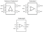
I'm also not aware of a TS391 type with the shown pin assignment. Thus it's not clear what are inverting and non-inverting input. Why did you introduce a new part instead of referring to the original problem definition?

ts391.PNG
 

The inputs to the OR logic should be these onesInputs.png
 

Hi,

Just to add to what FvM has already provided, the schematic below is a small variation of the same premise:

View attachment 154586

As this is only a simulation, although most work with occasional fine tuning of component values, skepticism never hurts. Simulators solve maths problems with idealised components.

Notice lovely ground bounce here and there, that's why I added the two Schottky diodes. One of life's necessary evils.

Hopefully, you should be able to use either schematic in the real world and get on with fine tuning pertinent details to your application now.

Good luck!

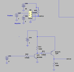
I have simulated this circuit with the first input the output of a comparator and it is not working as you show in the diagram. Could you help me?
 

Hi,

I have simulated this circuit with the first input the output of a comparator and it is not working as you show in the diagram. Could you help me?

Post #16 isn't the right one, I understand the schematic in post #18 fulfils the requirement. The requirement is still that either of two inputs when high make the output go low, right?

Could you post a schematic of the comparator circuit that you mention, please?
 

Hi,

The requirements depends of the outputs 20 and 12 (Post #25). The output 12 need to be inverted. In the #25 is wrong, it is not inverted.These outputs control the gate of the PMOSFET.
If one of these outputs is high the PMOSFET is shut down.
 

Hi,

You can just swap the comparator inputs over to invert the output.

If it won't work that way, I'd try using two equal devices as the PMOS gate controllers/drivers, e.g. Two NPNs.
Not sure why you chose a PNP when suggestions were NPNs, but if it produces the desired outcome, great.
 

Status
Not open for further replies.

Part and Inventory Search

Welcome to EDABoard.com

Sponsor

Back
Top