David_
Advanced Member level 2
Hello.
I acquired a sensor called S25P050D15X with the intention to use it in a circuit to measure the saturation current of ferromagnetic cores i.e. inductors and transformers, but my concern is this, the sensors datasheet can be found here.
Further down on page 2(the last page) there is this warning:
The thing is that I was relying on doing just that in order to make use of this sensor as it is rated for 50A and I will rarely if ever measure 50A, mostly I will probably measure below 5A but I wanted to be able to measure up to 50A while being able to measure much lower currents with a larger output response from the sensor by looping the primary multiple times through the core. Does anyone have any suggestions or insights into why this is prohibited?
I wonder if this restriction has something to do with the fact that this sensor is of the "closed loop type" as opposed to the "open loop type", as I am writing this that seems as a very plausible explanation.
The circuit that this sensor would be used in is often used to read the result directly on an oscilloscope but I was hopping to in the end enable a microcontroller to record the measurements and by some algorithm hopefully mostly be able to detect the knee in the waveform where the core saturates and the current as a result increases(and then display that value on a display of some sort). In ether case one solution might simply be to amplify the sensors output voltage to make it more discernable on the scope or the the µC's algorithm.
First I thought "what if I simply increase the output resistor to create a larger voltage across said resistor" but the datasheet states that the:
Measuring resistance =
60Ω~95Ω (at VCC= ±12V)
135Ω~ 155Ω (at VCC = ±15V)
So amplifying the voltage is perhaps the way to go, I was recommended to just buy a cheap sensor on ebay but oh no I wanted to buy a more expensive sensor to make more accurate measurements... I should have gone with a open loop type sensor.
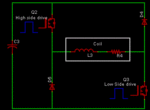
By the way, the attached circuit was posted by the member Warpspeed in a old thread I had in which he suggested that circuit instead of the usual single low-side switch + capacitor bank that you see all over the internet, I like the circuit Warpspeed suggested much more.
Any and all thoughts about this is very welcome.
Regards
I acquired a sensor called S25P050D15X with the intention to use it in a circuit to measure the saturation current of ferromagnetic cores i.e. inductors and transformers, but my concern is this, the sensors datasheet can be found here.
Further down on page 2(the last page) there is this warning:
CAUTION
Do not wrap the primary conductor around the core part of the product to increase measured current.
Do not wrap the primary conductor around the core part of the product to increase measured current.
The thing is that I was relying on doing just that in order to make use of this sensor as it is rated for 50A and I will rarely if ever measure 50A, mostly I will probably measure below 5A but I wanted to be able to measure up to 50A while being able to measure much lower currents with a larger output response from the sensor by looping the primary multiple times through the core. Does anyone have any suggestions or insights into why this is prohibited?
I wonder if this restriction has something to do with the fact that this sensor is of the "closed loop type" as opposed to the "open loop type", as I am writing this that seems as a very plausible explanation.
The circuit that this sensor would be used in is often used to read the result directly on an oscilloscope but I was hopping to in the end enable a microcontroller to record the measurements and by some algorithm hopefully mostly be able to detect the knee in the waveform where the core saturates and the current as a result increases(and then display that value on a display of some sort). In ether case one solution might simply be to amplify the sensors output voltage to make it more discernable on the scope or the the µC's algorithm.
First I thought "what if I simply increase the output resistor to create a larger voltage across said resistor" but the datasheet states that the:
Measuring resistance =
60Ω~95Ω (at VCC= ±12V)
135Ω~ 155Ω (at VCC = ±15V)
So amplifying the voltage is perhaps the way to go, I was recommended to just buy a cheap sensor on ebay but oh no I wanted to buy a more expensive sensor to make more accurate measurements... I should have gone with a open loop type sensor.
By the way, the attached circuit was posted by the member Warpspeed in a old thread I had in which he suggested that circuit instead of the usual single low-side switch + capacitor bank that you see all over the internet, I like the circuit Warpspeed suggested much more.
Any and all thoughts about this is very welcome.
Regards
