electronicnoob
Junior Member level 1
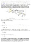
I found a schematic online that uses a lm2576 in a buck converter to regulate 2A of current.
I simulated the circuit and it is working perfectly. However, I have no idea on how this works and what is the function of each components. I have also read the website that posted this and i do not understand what has the gain got to do with the circuit.
Attached is the schematic and the information from the website

