Anomis
Junior Member level 3
- Joined
- Mar 11, 2017
- Messages
- 29
- Helped
- 5
- Reputation
- 10
- Reaction score
- 4
- Trophy points
- 3
- Location
- South Korea
- Activity points
- 294
Hi all,
I am studying some stuff related to wideband Circulator device in range of 2.3 to 2.5 GHz
and the question is how can i control isolation route (magnitude and phase) ? for example from Port 2 to port 1
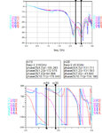
For what i ve done, to get insight, I bought a commercial Circulator and do analysis it with Network analyzer, but when i decapped off and solder it onto new and PCB, wierdly It did not provide the idential isolation (phase/magnitude) ( I want the phase here flatten as much as possible and same magnitude response when moving from this PCB to another PCB)
I confusedly do not know exact issues, i guess due to heating or area of ground plane of PCB but i can not say for sure what culprit is

is there anyone that played with it, please give me some advices ?
TM
I am studying some stuff related to wideband Circulator device in range of 2.3 to 2.5 GHz
and the question is how can i control isolation route (magnitude and phase) ? for example from Port 2 to port 1
For what i ve done, to get insight, I bought a commercial Circulator and do analysis it with Network analyzer, but when i decapped off and solder it onto new and PCB, wierdly It did not provide the idential isolation (phase/magnitude) ( I want the phase here flatten as much as possible and same magnitude response when moving from this PCB to another PCB)
I confusedly do not know exact issues, i guess due to heating or area of ground plane of PCB but i can not say for sure what culprit is

is there anyone that played with it, please give me some advices ?
TM
