T
treez
Guest
Hi
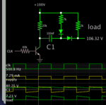
We need to switch some PWM dimming FETs on and off. These FETs sit on top of a 100V rail and the driving micro sits at 0V…therefore we need to translate the drive signal up in voltage.
We can either use a SI8710 digital isolator, or a IRS25752 bootstrap driver. The IRS25752 looks a hands down winner as its cheaper, smaller, and uses less bias current.
Can you think of any disadvantages of the IRS25752?
IRS25752
https://www.infineon.com/dgdl/irs25752lpbf.pdf?fileId=5546d462533600a40153567b388b2839
SI8710
https://media.digikey.com/pdf/Data Sheets/Silicon Laboratories PDFs/Si87xx.pdf
