Continue to Site

Welcome to EDAboard.com

Welcome to our site! EDAboard.com is an international Electronics Discussion Forum focused on EDA software, circuits, schematics, books, theory, papers, asic, pld, 8051, DSP, Network, RF, Analog Design, PCB, Service Manuals... and a whole lot more! To participate you need to register. Registration is free. Click here to register now.

Open circuit ground multiplexing?

Status
Not open for further replies.

brandon.tarr@restek.com

Newbie level 3
Joined
Dec 9, 2014
Messages
4
Helped
0
Reputation
0
Reaction score
0
Trophy points
1
Activity points
51
Hi all. I am experimenting with electrospray ionization. The setup has a 4kV power supply connected to an electrode that is separated from a return lug (or ground plate) via an air gap, followed by an inline pico-ammeter and finally ground. The way this works is that a small drop of solvent is applied to the electrode, the 4kV power supply is energized, and the solvent forms an aerosol electrospray "Taylor cone" between the electrode and return lug. When this is occurring (it is not especially visible except via laser light) the inline pico-ammeter reads somewhere on the order of 20-100 nA resulting from the ion transfer.

I would like to test a very large number of electrodes by systematically switching the pico-ammeter & ground between the various return lugs. My first thought was to use a multiplexer, but I'm not sure if this is even possible, and I have a few concerns. Specifically, iIs there a mux that can switch a ground reference (through the pico-ammeter) to an open (high impedance) circuit, and has a low enough on resistance as to not substantially effect the 20nA ion transfer current?

Also, every so often the air gap gets a little too small and turns into a 4kV "spark gap" which results in having to change a fuse in the pico-ammeter. What would be the best practices with regards to circuit protection for preventing this scenario from frying the switching circuitry?

Thanks in advance!
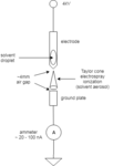
single electrospray.png multiplexed electrospray.png
 

First of all, you're measuring NANOamps with a PICOammeter?

I don't see any problem with this, in theory. You'll have to pay attention to the leakage current of the mux, which may be on the order of hundreds of pico-amps. I do believe, however, that there are devices with tens of pico-amps of leakage. You can get muxes with fairly low resistance, so I don't think that would be a problem. But I wold be concerned about the high voltage you are using. What voltage appears on the mux terminal when you get a spark?
 

The range of the pico-ammeter is pico (well technically I guess fempto since the resolution on the lowest scale is 100 fA) through milli, so yes, I'm measuring nA with a "pico-ammeter". Now, back to our regularly scheduled program...
 

For clarification, I already have a current measuring system, so I would rather not design one from scratch if it isn't necessary. I am specifically asking about the identification of multiplexer transistor architectures (if any) that are capable of switching ground to a no load, high Z or floating condition. (like a mechanical switch or relay but much faster and more scalable) Normally, low side switching with a low Rds On would be the job of an N-Channel Mosfet except they generally won't turn on with an unloaded drain pin. (to my knowledge) Are there any solid state switching topologies that are capable of this?
 

For clarification, I already have a current measuring system, so I would rather not design one from scratch if it isn't necessary. I am specifically asking about the identification of multiplexer transistor architectures (if any) that are capable of switching ground to a no load, high Z or floating condition. (like a mechanical switch or relay but much faster and more scalable) Normally, low side switching with a low Rds On would be the job of an N-Channel Mosfet except they generally won't turn on with an unloaded drain pin. (to my knowledge) Are there any solid state switching topologies that are capable of this?

But you don't have an "unloaded" drain pin; you've said that you've got current flowing. When there's no current flow it doesn't matter WHAT the architecture is. As far as I can see, this is no different than having a mux switch a circuit where's there's a switch in the load path.

There may be other concerns, such as charge buildup on mux pins, etc., but that's not clear to me.
 

I believe you didn't yet identify a serious problem of your topology. It's the required voltage rating of open switches. If you don't plan with 4 kV rated switches, you need additional short switches to ground or some kind of clamping circuit for the open channels.
 

I believe you didn't yet identify a serious problem of your topology. It's the required voltage rating of open switches. If you don't plan with 4 kV rated switches, you need additional short switches to ground or some kind of clamping circuit for the open channels.

If I understand this correctly, there should never be 4kV at the switch-essentially there's 4kV on the other side of an air-gap. But I did question this in post #2.
 

If I understand this correctly, there should never be 4kV at the switch-essentially there's 4kV on the other side of an air-gap. But I did question this in post #2.

That's correct. The air gap essentially acts like a really big resistor while the electrospray is happening. So, the low side circuitry will never see 4kV. If the air gap gets too small and turns into a spark gap, the plasma created by the arc will act as a much lower value resistor.

When the return plate is connected to ground, ~ 20uA of current flows through the ammeter as a result of the electrospray. This only occurs until all of the solvent is evaporated, at which point the current drops to zero. Simply energizing the 4kV supply on an electrode over a return plate that is connected to ground is not enough to induce a current. So, in this condition, there is no current.
 

That's correct. The air gap essentially acts like a really big resistor while the electrospray is happening. So, the low side circuitry will never see 4kV.

Error of reasoning. A high ohmic resistor connected to an open circuit has zero voltage drop, thus pulls the open circuit to 4 kV. Otherwise you need to short the open circuit to ground.

The question of practical interest is how much current may be maximal injected into the low side by the "big resistor". The consideration should include the case that you are activating the electrospray apparatus although the multiplexer didn't switch to the channel. You also mentioned possible air gap isolation break down. If this can happen, there should be a current limiting feature or a surge proof clamping circuit for the low side.
 

Status
Not open for further replies.

Similar threads

Part and Inventory Search

Welcome to EDABoard.com

Sponsor

Back
Top