Continue to Site

Welcome to EDAboard.com

Welcome to our site! EDAboard.com is an international Electronics Discussion Forum focused on EDA software, circuits, schematics, books, theory, papers, asic, pld, 8051, DSP, Network, RF, Analog Design, PCB, Service Manuals... and a whole lot more! To participate you need to register. Registration is free. Click here to register now.

DC blocking capacitors or interdigital capacitors at 24 GHz

Status
Not open for further replies.

sMalla

Newbie level 2
Joined
Jun 25, 2019
Messages
2
Helped
0
Reputation
0
Reaction score
0
Trophy points
1
Activity points
21
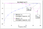
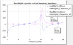
I am looking at dc blocking caps at 24 GHz. I am having a tough time finding the capacitors that have their SRF above 24 GHz. So, I was looking at interdigital caps using microstrip lines at 24 GHz. My substrate is Rogers 4350B, thickness is 0.254 mm. I would like to design an interdigital capacitor for 0.33pF and 0.39pF. Could anyone provide the design methodology for this interdigital capacitor. This capacitor will be used as a DC block in an LNA application using CE3520K3 FET.
 

This is what a friend created 20 years ago, substrate quite similar to yours.
Curves are simulated and measured S11 and S21.

I cant share more details, but maybe this gets you started.

icap_24.jpg
 

Thank you volker. I had created an interdigital filter similar to that in AWR MWO and run the EM extraction. I had obtained results similar to yours, but mine requires some tuning. Below, you will find the return loss and the insertion loss curves.
l8kksoW.png

But, I have a question with the impedance curve. Please see the attached real and imaginary impedance curve.
9e4ABh8.png

The real and imaginary curves peak at 16 GHz. What could be the reason for this and what does this mean? Also the imaginary impedance at 24 GHz is 14.4 ohms, indicating an inductive component. So if I were to use this interdigital capacitor in a circuit, does it function as a capacitor at all the frequencies?
 

Attachments

  • Interdigital cap for eda board.PNG
    Interdigital cap for eda board.PNG
    33.4 KB · Views: 148
  • Interdigital cap for eda board impedance.PNG
    Interdigital cap for eda board impedance.PNG
    36.8 KB · Views: 129

Also the imaginary impedance at 24 GHz is 14.4 ohms, indicating an inductive component. So if I were to use this interdigital capacitor in a circuit, does it function as a capacitor at all the frequencies?

If the element passes 24GHz RF with good S11 and blocks DC, that should be fine. Once you have optimized the layout, you will have small series impedance. At lower frequencies, it will be capacitive, with effectice C increasing towards 24GHz.

- - - Updated - - -

If you have inductive response, maybe you simulated the device as a 1-port (between the terminals on both ends) where all the physical length translates into a series inductance? I don't think that's a useful method to characterize this distributed device. I would look at the 2-port parameters.
 

Status
Not open for further replies.

Part and Inventory Search

Welcome to EDABoard.com

Sponsor

Back
Top