Continue to Site

Welcome to EDAboard.com

Welcome to our site! EDAboard.com is an international Electronics Discussion Forum focused on EDA software, circuits, schematics, books, theory, papers, asic, pld, 8051, DSP, Network, RF, Analog Design, PCB, Service Manuals... and a whole lot more! To participate you need to register. Registration is free. Click here to register now.

LTspice: Modelling a negative resistor

Status
Not open for further replies.

Swend

Full Member level 4
Joined
May 14, 2019
Messages
237
Helped
10
Reputation
20
Reaction score
9
Trophy points
18
Location
Roskilde, Denmark
Activity points
2,304
Hi friends

For some theoretical LTspice work I need a model for a voltage controlled resistor that can produce both negative and positive resistance.

I thought of making a SUBCKT with a negative impedance converter made up of a single op-amp, but I think that kind of limits it's application. I would like it to be more simple and versatile like the ubiquitous resistor model in LTspice, would that be possible and what approach would most suitable?
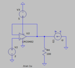
 

You mean modelling a voltage controlled negative resistor in the simulator in contrast to designing a real circuit that exposes a negative resistance?

It can be most easily done with a behavioral current source. I = x*V
 
  • Like
Reactions: Swend

    Swend

    Points: 2
    Helpful Answer Positive Rating
You mean modelling a voltage controlled negative resistor in the simulator in contrast to designing a real circuit that exposes a negative resistance?

Yes

It can be most easily done with a behavioral current source. I = x*V

Yes I see it now, you mean e.g. like this?

Screenshot from 2019-06-25 10-51-28.png
 

Not specifically, review help for "B. Arbitrary Behavioral Voltage or Current Sources"

Sorry, that's just me assuming you can read my mind. On the left voltage follower with 100ohm load. On the right current source to simulate negative resistance, cancelling out the 100ohm. Obviously some voltage needs to control the current source, so it's just meant as illustrative.
 

Several years ago I have modelled a voltage-controlled resitor in PSipce using a voltage-controlled current source.
Both output nodes of the source (1,2) were used to specify the VALUE of the current source as a function of the VOLTAGE between both nodes (1,2) divided by a the control voltage.
The direction (sign) of the current defines the resistor between the nodes as positive or negative.
This works for a constant or only time dependent resistor. If the resistance is also a function of another node voltage or branch current, it has to be implemented by a behavioral expression, most simply with a B source.
 

Status
Not open for further replies.

Part and Inventory Search

Welcome to EDABoard.com

Sponsor

Back
Top