Continue to Site

Welcome to EDAboard.com

Welcome to our site! EDAboard.com is an international Electronics Discussion Forum focused on EDA software, circuits, schematics, books, theory, papers, asic, pld, 8051, DSP, Network, RF, Analog Design, PCB, Service Manuals... and a whole lot more! To participate you need to register. Registration is free. Click here to register now.

Transimpedance and Potentiostatic circuit oscillations

Status
Not open for further replies.

eengr

Member level 4
Joined
Mar 9, 2016
Messages
75
Helped
0
Reputation
0
Reaction score
0
Trophy points
1,286
Activity points
4,270
Hi
I am trying to interface an O2 Electrochemical sensor on my board.

I have used potentio-static & transimpedance amplifier configuration.

I have tried to use what I found in number of application notes online.

My circuit is as shown in the picture
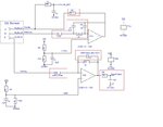
potentostat_transimpedance.jpg

Rail bypass caps of 100nF & 1uF not shown in this circuit but they are present on actual board

I am not an expert in circuit design so still learning.


The sensor requires bias boltage of apprx -300mV to -600mV. So working electrode is apprx 382mV less than Reference Electrode
I chose R3&R4 to get 1.777VDC as my bias voltage for Reference electrode
I chose R1 &R2 to get 1.395VDC as my bias voltage for Workingelectrode

Rgain (R7) (I used as 1K here although I would like to be bit more Gain but I could live with 1K for now if I could get this circuit to stable condition.)

Rload (R6) - I was advised by manufactuerr to use 100R to 470R. So I have tried both values and in between

I am not entirely sure how best to calculate C(feedback) (C6) but I saw one application note online which gave a formula like
feedback cap.jpg

In my case manufacturer does not provide the value of (C_s), but I have found in same application note & one from Alphasense that for electrochemical sensors the Capcitance of Working Electrode could be from 1mF to 300mF

Regarding OPAMPs I have tried MCP6032 which has GBW of 10kHz
I have also tried AD8607 which has GBW of apprx 350kHz

For MCP6032 I first used 100nF (C_feedback) (C6). & then I found the above formula and decided to use 10uF

For AD8607, I have used 100nF only

I have not got a slightest clue how the feedback Caps & Resistor values are chosen for potentiostatic side (R9, C4, R10, C5) & also the resistor R11. I just used what I found in some circuits online. (Not a great way to doing but I could not find a step by step guide or design notes)


All component values are as shown in the picture.

I have stability issues where my rails keep collapsing and I don't see my DC reference levels as expected.

Could someone please guide me in how to tackle this problem. What is the usual way of selecting the suitable component values for this kind of application to fix the oscillation problem.
As soon as circuit goes unstable, it starts taking to much current at 3.3V supply and does not allow me to take any meaningful measurements to start troubleshooting.
 

The described "stability" problem sounds like insufficient supply bypass capacitors for the OP or bad PCB layout.

Stability of the potentiostat circuit is partly affected by Rload. The value of 100 to 470 ohm in your circuit is a bit out of the ball park, 10 ohm is more typical, Alphasense AN105 e.g. suggests 10 to 100 ohm.
 
  • Like
Reactions: eengr

    eengr

    Points: 2
    Helpful Answer Positive Rating
The described "stability" problem sounds like insufficient supply bypass capacitors for the OP or bad PCB layout.

Stability of the potentiostat circuit is partly affected by Rload. The value of 100 to 470 ohm in your circuit is a bit out of the ball park, 10 ohm is more typical, Alphasense AN105 e.g. suggests 10 to 100 ohm.

Yes I originally started with using 10R Rload from your mentioned alpha sense note but it was oscillating.
I was then advised to use 100R to 470R
I have used high value bypass caps like tantalum 47uF and removed all on board regulators so powering directly from benchtop TTI power supply.

I have done similar circuitry using LM7721 Opamp that has GBW of 10MHz and that has worked but that package is too big for this application. Although I again used
most component values from application notes rather doing any calculations. Are there any guidelines for components value calculations for these type circuits?
 

I don't remember ever having problems with stability of potentiostatic circuits, but it's 10 or 15 years that I worked on this field. It makes sense to analyze the oscillation frequency and find out how an oscillation, particularly with high current consumption can happen at all.
 

I don't remember ever having problems with stability of potentiostatic circuits, but it's 10 or 15 years that I worked on this field. It makes sense to analyze the oscillation frequency and find out how an oscillation, particularly with high current consumption can happen at all.

I have done three different revisions on PCBs just to tackle this issue. The board also have other digital circuit like uC and memory etc. But then I decided just do a standalone board for this. Through out the testing these different boards, I have been experiencing this high current problems and not be able to get the bias voltage stable at one level even by removing everything else from board (but keeping these two Opamp and components around them)

I have also tried generating the bias reference voltages from a fixed voltage reference REF3325 from TI, but it also showed same problems.

At one stage I noticed that (and this was quite repeatable when this happened) that when high current was consumed from 3.3V rail, my rail capacitors appeared very low impedance (like 25 ohms -- I measured this with DMM after removing the supply), but this value started increasing as my DMM was across the rail (3.3V and 0V). And after an hour or so, it would go to >2K ohms and then when I apply 3.3V across, the same rail collapsing would happen (this was all across ceramic caps).
But if I disconnect these caps and just put them directly across 3.3V from same power supply, they would work just fine. Only when they are in circuit they start appearing as very low impedance on application of 3.3V across them. All of them were rated >25V. And I ordered different batches from different suppliers and still having same problems.


For Opamps Vcc I have also tried connecting like 10R or 27R in series with 3.3V and Vcc pin with 1uF & 0.1uF from Vcc to ground. But when this over current thing happens, the voltage from Vcc pin to ground collapses to less than 1V (as if it is loading it) (0402 caps and resistors mostly)
I have tried bigger value rail 47uF tantalum reservoir caps but no luck.

That's when I started investigating it on stability side and I thought that it is Opamp being unstable that is causing it. And the fact that design was more based on following what others have loaded on internet rather me doing the calculations to get the optimum component values made me think more that it has do with my components selection more than anything. (Plus the fact that the similar circuit except the Opamp itself works for same rail caps and similar layout, when I use LM7721 Opamp)
Whosoever I spoke to, have never observed ceramic caps changing their impedance with DC power supply connected across them in circuit... So basically I am stuck and need to find a way out...
 

Has anyone here had any such issues with Rail ceramic caps going low impedance when plugged in circuit and then back high impedance when voltage is taken off? Or if it is happening because the Opamp is going unstable and causing the rails to load heavily!?
 

Sounds unlikely and not in accordance with known capacitor behavior. More likely an OP sinks high supply current during high frequent oscillations, even without a low impedance load.
 
  • Like
Reactions: eengr

    eengr

    Points: 2
    Helpful Answer Positive Rating
OK i took some traces.

I first built Potentiostatic circuit only. The OPAMP used in this case was SOT-23 LPV821

potentostat_transimpedance_2nd.jpg

I used R13 & R14 as 11K & 13.3K respectively. I used 10uF cap as C1.

I also closed the loop of OPAMP by connect a short-link wire between Counter Electrode & Reference Electrode (So No gas sensor was used, just opamp with 10K (R11) + 10K(R9) in feedback path

For a minute or so, i have seen solid 1.78V across C1 (as VRef), but then it just started collapsing. I took a trace as follows:

NewFile1.jpg

(Yellow is my 3.3V, Blue is my V+ of Opamp IC1b (across C1), Pink is my output (Pin-1 of same opamp) (Ignore the noise on Pink trace as it was noise pickup from my desktop lamp)

& this was only one instance of measurement, the trace of V+ (across C1) took all sorts of of funny shapes

I then took off capacitor C1 (measured it using Cap meter and it showed apprx 11uF)

I powered ON circuit without it, & it stayed stable for few minutes before voltage V+ (non-inverting input) collapsed again

I switch ON/OFF multiple times, sometimes, it would switch ON stable and then collapse after few seconds and other times it would power up with apprx 0.2V to 0.4V at non-inverting input

I then put 10uF Cap back in (at C1). & all of sudden it become stable. I switched ON/OFF multiple times and no issues found.

I then decided to assemble the transimpedance amp (TIA) side.

I used 10K & 7.32K for R1 & R2. Used 10uF for C2. Opamp as LPV821. R7= 11K, C6=10uF

I switch ON circuit again and monitored Vref (non-inverting inputs) of both Opamps -- Potentiostat & TIA

But they were all over the place. Took few traces:

Yellow: 3.3V Rail
Pink: TIA Ref (across C2)
Blue: Potentiostat Ref (across C1)


NewFile2.jpg

(The above is taken at Power UP. See Blue trace goes down after few seconds)

NewFile3.jpg
(The above is taken at random time whilst circuit was still powered. See Blue trace goes UP/down randomly)
NewFile4.jpg
(The above is taken again at POWER UP. The trace on Right of Dip in middle is after Power Up)
NewFile5.jpg
(The same as last trace but on different time scale)


As you can see above the two references are all over the place, it does not make any difference if I take the 10uF OFF or leave them ON. Well it makes difference in as much as that shape of these spikes change slightly because of Caps charging/discharging, but they dont stay stable.

Interstingly, throughout these tests my 3.3V staed stable and I did not see any collapsing there. I used 10R in series with Vcc pins of each Opamp & 1uF & 100nF reail bypass caps

Any help would be greatly appreciated
 

Attachments

  • potentostat_transimpedance_2nd.jpg
    potentostat_transimpedance_2nd.jpg
    68.6 KB · Views: 86

Hi,

Some of your scope pictures don't show normal Opaamp behaviour.
My first guess: bad solder joints.

Can you show us a detailed photo of your circuit with all your connections (including scope)

Klaus
 
  • Like
Reactions: eengr

    eengr

    Points: 2
    Helpful Answer Positive Rating
Hi,

did you bypass the supply of the OPAs? I remember some weird behavior by an OPAmp because I forgot to bypass the voltage on both supply rails. I think I solved the issues by putting in two tantalums with 10uF.

Can we see the layout?

Johannes
 
  • Like
Reactions: eengr

    eengr

    Points: 2
    Helpful Answer Positive Rating
Hi,

Some of your scope pictures don't show normal Opaamp behaviour.
My first guess: bad solder joints.

Can you show us a detailed photo of your circuit with all your connections (including scope)

Klaus


Yes you were absolutely correct. It was assembly issues that was causing these problems. I saw the board under the visual inspection camera and it was awful. Dry joints, too much flux. I now repaired the joints and thoroughly cleaned the board and the first board is working fine now. Thank you very much for your and others kind help.

Now, my other question about the component selection especially for resistors R11, R9, R10 & Capacitor C4 & C5 around the potentiostat in my original schematic.
How do we determine / calculate the optimum values for these components.

I found a note in one application note that says:
R11 is to maintain stability due to the large capacitance of the sensor.
C4 and R9 form the Potentiostat integrator and set the feedback time constant.

But say I have Sensor's capacitance of 1milli-Farad,

My Opamp GBW= 8kHz
& My opamp Z(out) = 80 kohms
Aol = 135dB

Then how would I calculate the value of these feedback components?
 

Status
Not open for further replies.

Similar threads

Part and Inventory Search

Welcome to EDABoard.com

Sponsor

Back
Top