Continue to Site

Welcome to EDAboard.com

Welcome to our site! EDAboard.com is an international Electronics Discussion Forum focused on EDA software, circuits, schematics, books, theory, papers, asic, pld, 8051, DSP, Network, RF, Analog Design, PCB, Service Manuals... and a whole lot more! To participate you need to register. Registration is free. Click here to register now.

How to correctly calculate coil's field strength?

Status
Not open for further replies.
You wrote earlier that it will be pulsed, in connection with power/ heat dissipation concerns which were raised by me.

Hence my question.

50amps into 1.1ohm implies 2.75Kw which is not trivial.
 

You wrote earlier that it will be pulsed, in connection with power/ heat dissipation concerns which were raised by me.

Hence my question.

50amps into 1.1ohm implies 2.75Kw which is not trivial.
I am aware of that, that's why duty cycle will be 50% or less, but that's irrelevant for my question.

- - - Updated - - -

Dimensions 110mm x 23.8mm 425 turns, same current, same gap in the center of 4cm.
 

I am aware of that, that's why duty cycle will be 50% or less, but that's irrelevant for my question.

I suppose it's irrelevant if you're not actually planning to make such a device. Even with Duty cycle <50% it is important to know the repetition rate. For e.g. a rep rate of 1 / minute and duty 25% means it is ON for 15 seconds continuously.

You are generating 2750 joules of heat per second, and your coil is capable of dissipating not more than around 40 watts in air with a 50 degC temp differential. You would need some significant additional heat disposal system in place.

Also, to achieve 50 amps, you need at least 55 volts PS.

Just saying

Qustion is about flux density, not heat dissipation, but since you insist on it, how do you think 1Ohm or even 0.5Ohm speaker coils dissipate heat if they are not able to dissipate more than 40 watts as you say.

Most of the energy in the speaker is Ohmic losses, small part of it is reactive losses. So where's the "burning heat" you speak about.

Also, this is wrong.

"For e.g. a rep rate of 1 / minute and duty 25% means it is ON for 15 seconds continuously."

25% DC means just that, out of every cycle only 25% of the time current flows, never 15sec cont.

As for 55V PS why even mention the obvious God knows.
 
Last edited:

Qustion is about flux density, not heat dissipation, but since you insist on it, how do you think 1Ohm or even 0.5Ohm speaker coils dissipate heat if they are not able to dissipate more than 40 watts as you say.

Most of the energy in the speaker is Ohmic losses, small part of it is reactive losses. So where's the "burning heat" you speak about.

I wrote that your coil can dissipate around 40 watts unassisted. Speaker coils also do heat up, and special design considerations have to be implemented so that they don't burn up or melt. I have never heard of 1 ohm / 0.5 ohm speakers.

Also, this is wrong.

"For e.g. a rep rate of 1 / minute and duty 25% means it is ON for 15 seconds continuously."

25% DC means just that, out of every cycle only 25% of the time current flows, never 15sec cont.

I am puzzled. Why do you say that 25% of 1 minute is not 15 seconds ?

As for 55V PS why even mention the obvious God knows.

Simply because you earlier wrote that you were procuring a 48v/ 20A PS for this specific purpose.
 

I wrote that your coil can dissipate around 40 watts unassisted.

And that's what i referred to, your claim that they cannot dissipate more than 40 watts unassisted.

Speaker coils also do heat up, and special design considerations have to be implemented so that they don't burn up or melt.

They do heat up, but rarely to a point of being hot. Only if driven at high power for long time.

I have never heard of 1 ohm / 0.5 ohm speakers.

https://www.amazon.com/Kicker-CompRT-6-75-1-Ohm-Subwoofer/dp/B01BLVEZG6

I am puzzled. Why do you say that 25% of 1 minute is not 15 seconds ?

That's not what i said. I said there is no 15 second continuous load as you said.

Simply because you earlier wrote that you were procuring a 48v/ 20A PS for this specific purpose.

Parameters changed.
 

Very interesting about those Kicker speakers. Thanks for bringing them up in this thread.

I notice that these are dual voice coils, hence rms power per coil would be half of the stated 150 watts rms.

So for a nominal car battery of 12volts, we could achieve (12+12)^2 / 8 / 1 = 72 watts rms per coil with a class-D amp. At a current draw of 12 amps peak per coil, hence 24 amps peak total for dual coil.

They also specify that the coils have "Double venting for max cooling" and "High-temp voice coil for increased power handling" and "Perimeter venting causes a vortex cooling effect" and also "Blackened One Piece Uniplate with Vented Hyper-Extended Pole provides enhanced heat transfer for cool operation and maximum power handling. The heat is transferred from the pole piece to the back plate, effectively acting like a radiator in an engine. This lowers the operating temperature of the voice coil".

Clearly heating is an issue (obviously), and I re-iterate - requires special design considerations to ensure it is kept under control.

And this is just for 150 watts. The designers know that this is for music, so typically will not be driven to those extremes for great lengths of time, and hence might be overstating the capability. Whereas your coil (which is of approximately similar dimensions) is in the region of 1000-1500 watts, based on assumptions regarding your 'pulsing'. This is an order of magnitude greater.

In addition, since the coil inductance will be around 10mH, hence you will need a pulse ON duration of > 30mS to reach your target of 50 Amps.

Just saying.
 

You're most welcome. Yes, i noted it is "only" 150 watt RMS.

As for power dissipation in speaker coils, it is an interesting question, if you ask it at yahoo answers like i did you will get a bunch of conflicting answers.

The one i chose as best said 75% of energy is due to ohmic losses and the rest due to acoustic vibrations (and a tiny amount as radiation).

This implies those 25% of acoustic vibration work is being added to normal ohmic losses which are there whether coils vibrates the membrane or not.

As for my coil it is supposed to work against a fixed PM (neutralizing it), so question is whether coil sees this as work.

Power will be ajdusted to acceptable value by duty cycle and amplitude, i will probably go with less than 50 amps and less than 50% duty cycle.

As for reactance there will be very little as i will drive it at resonant frequency.
 

... if you ask it at yahoo answers like i did you will get a bunch of conflicting answers.
The one i chose as best said 75% of energy is due to ohmic losses and the rest due to acoustic vibrations (and a tiny amount as radiation).
This implies those 25% of acoustic vibration work is being added to normal ohmic losses which are there whether coils vibrates the membrane or not.
As for my coil it is supposed to work against a fixed PM (neutralizing it), so question is whether coil sees this as work.

In your case we are considering only ohmic power.

Power will be ajdusted to acceptable value by duty cycle and amplitude, i will probably go with less than 50 amps and less than 50% duty cycle.

Once again, to achieve upto 50 amps, you need a time of ~30mS given that L ~ 10mH with a PS of ~60V. Similar time for current ramp down. More time if you want to keep the heating under check.
Hence repetition rate will have to be >60mS at least, which is <= 16 Hz

As for reactance there will be very little as i will drive it at resonant frequency.

This concept is beyond my technical capabilities
 

Which part of no reactance you don't understand. At resonant frequency, only ohmic losses matter, no inductive or capacitive reactance.
 

Which part of no reactance you don't understand. At resonant frequency, only ohmic losses matter, no inductive or capacitive reactance.

It is not clear what "resonance" you are talking about, or what "capacitive reactance" is there in your setup.

To drive a 10mH inductance from Zero current upto 50 amps using a constant voltage power supply requires ~30mS. How you intend to somehow short circuit the inductance and achieve 50 amps using some mysterious reactance in less time than 30mS is beyond my understanding.

Just saying

Seems you don't understand the meaning of reactance. Which 10mH are you talking about, where did you pull that from.

If driven at resonant frequency, coil's capacitive and inductive reactance cancel out, it behaves as if driven by DC.

XL= 2πfL
XC= -1/2πfC
Z = sqrt(R² + (Xc - Xl)²)
F = 1/6.28(LC)
F = 1/2π√LC

What's confusing you about this simple concept is beyond me.
 

Seems you don't understand the meaning of reactance. Which 10mH are you talking about, where did you pull that from.

from here... where the estimate is 8.67mH, which I rounded to 10mH for easy writing.

Capture.JPG

If driven at resonant frequency, coil's capacitive and inductive reactance cancel out, it behaves as if driven by DC.

XL= 2πfL
XC= -1/2πfC
Z = sqrt(R² + (Xc - Xl)²)
F = 1/6.28(LC)
F = 1/2π√LC

What's confusing you about this simple concept is beyond me.

These equations are irrelevant.
 

from here... where the estimate is 8.67mH, which I rounded to 10mH for easy writing.

View attachment 154217

These equations are irrelevant.

LOL inductance of this coil is nowhere near 8.67mH.

Reactance being 0 at resonant frequency is anything but "irrelevant".
 
Last edited:

LOL inductance of this coil is nowhere near 8.67mH.

I would be interested to know what your estimate is ? I simply used a freely available software to estimate. Maybe you have measured it more accurately ?

Reactance being 0 at resonant frequency is anything but "irrelevant".

If your resonant frequency is below 16 Hz, then this might prove useful. However to achieve resonance below 16 Hz for a 10mH inductor would require a capacitance of 0.01 farads. I doubt this is feasible, and hence I said it was irrelevant.
 

I would be interested to know what your estimate is ? I simply used a freely available software to estimate. Maybe you have measured it more accurately ?

Inductance for 1 layer of this coil is 50uH, for 17 layers it is ~850uH or 0.85mH.

For calculation i used this website kaizerpowerelectronics.dk/calculators/spiral-coil-calculator/


If your resonant frequency is below 16 Hz, then this might prove useful. However to achieve resonance below 16 Hz for a 10mH inductor would require a capacitance of 0.01 farads. I doubt this is feasible, and hence I said it was irrelevant.

What are you on about God only knows. 16Hz??

Resonant frequency for this coil is expected to be in range of ~5KHz.

At that frequency coil will behave as pure resistor and thus no-reactance matters very much.
 

Inductance for 1 layer of this coil is 50uH, for 17 layers it is ~850uH or 0.85mH.

For calculation i used this website kaizerpowerelectronics.dk/calculators/spiral-coil-calculator/

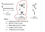
How very interesting. When I applied the same dimensions of your coil to your referred website with Wheeler's formula, I obtained L = 10.132 mH !
Of course I correctly used the formula given for a multilayer coil, rather than your simpleton's application of spiral coil formula multiply by # supposed spirals.

See pic below if you cannot understand words. Its the bit outlined with red line.

Capture1.JPG

What are you on about God only knows. 16Hz??
Resonant frequency for this coil is expected to be in range of ~5KHz.
At that frequency coil will behave as pure resistor and thus no-reactance matters very much.

I calculate 16 Hz because it takes 30mS to ramp up to 50 amps into 10mH at 60V. Hence 50% duty cycle implies 60mS implies 16.67 Hz
I have repeated this many times now. Why is this so hard to understand ??? Clearly you are not paying attention to what people are writing in your thread.

Also, I am really curious to know where you came up with this frequency of ~5Khz as resonant freq of coil. This implies a capacitance of 100nF (if L = 10mH), and capacitance of 1.2uF (if L = 0.85mH as you say). Both are obviously wrong, hence your "resonant" frequency is wrong.

Lastly - please read up on the difference between inductance and inductive reactance.

bye bye
 

How very interesting. When I applied the same dimensions of your coil to your referred website with Wheeler's formula, I obtained L = 10.132 mH...
I calculate 16 Hz because it takes 30mS to ramp up to 50 amps into 10mH at 60V. bla bla bla


WOW, you actually managed to input few simple values into a simple formula i did not to happen to come accross, simpleton chimp.

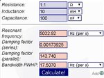
Let's see what's the actual resonance. If we take 10mH as actual inductance, resistance 1.1Ohm and assume capacitance to be small due to round wire, let's say 100nF, according to RLC calculator resonance is 5032.92Hz, exactly 5KHz as i assumed.

resonance.jpg

You not only need to learn the difference of inductance and inuductive reactance, you need to go back to kindergarden and start from a scratch, maybe even restart the whole incarnation.

Bye bye and enjoy your bannanas ;)
 

WOW, you actually managed to input few simple values into a simple formula i did not to happen to come accross, simpleton chimp.

Let's see what's the actual resonance. If we take 10mH as actual inductance, resistance 1.1Ohm and assume capacitance to be small due to round wire, let's say 100nF, according to RLC calculator resonance is 5032.92Hz, exactly 5KHz as i assumed.

View attachment 154221

You not only need to learn the difference of inductance and inuductive reactance, you need to go back to kindergarden and start from a scratch, maybe even restart the whole incarnation.

Bye bye and enjoy your bannanas ;)

This is absolutely brilliant. Please post your progress with this project regularly. We are all wanting to see how it finally turns out, and see you achieve your objectives. Which you will not of course.
:popcorn:

Thanks for the bananas !!!
ooka ooka !

- - - Updated - - -

Let's see what's the actual resonance. If we take 10mH as actual inductance, resistance 1.1Ohm and assume capacitance to be small due to round wire, let's say 100nF, according to RLC calculator resonance is 5032.92Hz, exactly 5KHz as i assumed.

Absolute genius
 

Thread preliminarily closed.

It may be reopened later. I feel that the original question has been answered in detail.
 

Status
Not open for further replies.

Part and Inventory Search

Welcome to EDABoard.com

Sponsor

Back
Top