Continue to Site

Welcome to EDAboard.com

Welcome to our site! EDAboard.com is an international Electronics Discussion Forum focused on EDA software, circuits, schematics, books, theory, papers, asic, pld, 8051, DSP, Network, RF, Analog Design, PCB, Service Manuals... and a whole lot more! To participate you need to register. Registration is free. Click here to register now.

[SOLVED] Voltage to frequency converter - problem with simulation

Status
Not open for further replies.

Cap_J

Newbie
Joined
Jun 8, 2019
Messages
5
Helped
0
Reputation
0
Reaction score
0
Trophy points
1
Activity points
48
Hello!
I'm trying to simulate circuit as below and it just doesn't work as described. This circuit should convert voltage (0-10 V) to frequency (0-10 kHz), so 1 V per 1 kHz. Maybe there is something wrong with this circuit?
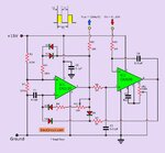
Voltage-to-Frequency-Converter-Circuit.jpg

I found this circuit on this website and also there is full description of this project: https://www.eleccircuit.com/voltage-to-frequency-converter-circuit/

I'm using Proteus 7.6 SP4 to simulate this circuit because only this software is available in my school.

I know that there is really great precision voltage to frequency converter like LM331 but I want to make this circuit in smaller scale of integration.

I would be glad if someone answer my question.
 

I assume when you say it doesn't work means your output is a flag dc signal?
I suggest you to probe the in/output signals of each IC and check which signal is not in expectation for debug purpose.
 

A REAL oscillator uses circuit noise to begin oscillating. A simulation has no noise so oscillation does not begin. In a simulation you need to add a pulse (a kick) to the input for oscillation to begin.

EDIT: Oh, the About Us on the ElecCircuit.com has the owner admitting that he has poor English and a person commenting says the owner is a novice in electronics. I think in India. Then maybe this circuit Does Not Work.
 
Last edited:

So, I connect DC generator to the input (Vin) and oscilloscope to the output (Fout) of this circuit.

If I set Vin to 1V - I get nothing on output (Fout).
1V_vin_doesnt-work.png

If I set Vin to 2V - I need to wait few minutes until input voltages will be at the same level and then I can see output signal (Fout).
2V_vin-waiting.png

If I set Vin to 3V - I get output signal (Fout) instantly at the start of simulation.
3V_vin_working.png

If I set Vin to 4V - I need to wait minute/two until input voltages will be at the same level and then I can see output signal (Fout).
4V-vin-need_to_wait.png

If I set Vin to 5V - I get output signal (Fout) instantly at the start of simulation.
5V_vin_working.png

If I set Vin to 6V - I get output signal (Fout) instantly at the start of simulation.
6V-vin_working.png

If I set Vin to 7V - I need to wait 5-6 seconds until input voltages (on the right op-amp IC) will be at the same level and then I can see output signal (Fout).
7V_vin-5sec-wait.png

If I set Vin to 8V, 9V and 10V - I get nothing on output (Fout).
8V_vin_doesnt-work.png
9V_vin_doesnt-work.png
10V_vin_doesnt-work.png

Any ideas?
 

I played a little with the circuit, and I couldn't get more than a 2:1 variation in output frequency.
I think it's a poorly designed circuit.
I suggest you look for something else.
What frequency range do you want?
 

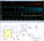
Here's the LTspice simulation of a 555 timer configured as a VCO.
It uses a Howland constant-current source to generate a charging current for the C2 timing capacitor proportional to the In voltage.
It's maximum frequency is near 11kHz with 10V input for the shown component values.

Capture.PNG
 
  • Like
Reactions: Cap_J

    Cap_J

    Points: 2
    Helpful Answer Positive Rating
Thank you so much! Now it's working pretty well :).
 

Status
Not open for further replies.

Similar threads

Part and Inventory Search

Welcome to EDABoard.com

Sponsor

Back
Top