Continue to Site

Welcome to EDAboard.com

Welcome to our site! EDAboard.com is an international Electronics Discussion Forum focused on EDA software, circuits, schematics, books, theory, papers, asic, pld, 8051, DSP, Network, RF, Analog Design, PCB, Service Manuals... and a whole lot more! To participate you need to register. Registration is free. Click here to register now.

[SOLVED] Generating more EMI due to BLDC motor

Status
Not open for further replies.

BoopathiS

Member level 2
Joined
May 18, 2018
Messages
44
Helped
1
Reputation
2
Reaction score
0
Trophy points
6
Activity points
484
HI,
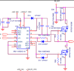
I'm controlling BLDC motor(Blower) using Half bridge driving circuitry. When running only blower during EMI testing, at 63MHz frequency more EMI noise is producing(6db more than limit).

Half bridge driver circuit switching frequency is 30kHz and Gate resistor is 100 ohm. Driver is controlled by microcontroller with 72MHz internal clock frequency.

Can you please clarify below points,

1. Whether 100ohm gate resistor is suitable for 30kHz switching frequency ? If i'm changing Gate resistor or Switching frequency can help me in EMI reduction?

2. 63Mhz is 2000 times the switching frequency. considering this switching circuit will create this much multiplied noise ?

3. Blower is the load. Is this one as EMI source ?

4. Without running the blower EMI is within limit(Standby condition, only microcontroller is in ON state), hope microcontroller internal oscillator will not create any EMI source. My assumption is correct ?

Parallely, I'm looking into wire routing, PCB layout and component placement.

Schematic: IR2110 driver.PNG
 

Hi,

Generating more EMI due to BLDC motor
Not the motor is the problem, but the control unit.

1. Whether 100ohm gate resistor is suitable for 30kHz switching frequency ?
There is no general rule, thus it's hard to say.
Btw: Your fastest switching edge will be the switch OFF edge .... without the 100R in series.

If i'm changing Gate resistor or Switching frequency can help me in EMI reduction?
Most probably yes. The easiest may be to modulate the switching frequency a bit --> spread spectrum.

2. 63Mhz is 2000 times the switching frequency. considering this switching circuit will create this much multiplied noise ?
Obviously it will be the cause. An ideal square wave consists of infinitely high frequencies but with decreasing amplitude.
The problem will be some resonances...on the PCB, the wiring...

3. Blower is the load. Is this one as EMI source ?
As already said. I assume not, because a BLDC motor is a passive device, it can't generate high frequencies.

4. Without running the blower EMI is within limit(Standby condition, only microcontroller is in ON state), hope microcontroller internal oscillator will not create any EMI source. My assumption is correct ?
Maybe. Maybe PCB layout, maybe just some accidental interference, maybe the power supply...

Parallely, I'm looking into wire routing, PCB layout and component placement.
Yes, you could have posted some pictures.

I see a lot of guessing from your side. Why? Why don't you do some measurements. A narrow 63 MHz filter, a suitable scope...and you are able to check node by node...

Or simple test with a ferrite across the motor wires, or a shielded cable...

63MHz ... is about 4.75m wave length.
Or 2.38m lambda/2
Or 1.19m lambda/4
Is your cable length equal to one of these lengths?

Klaus
 
Hi,

KlausST Thank you so much for all your answers, its more useful for me.

Really not having idea of how to test/debug this. That's why guessing some root causes.

Motor cable length is 17cm.

I'm using shielded cable for BLDC motor. but ferrite core i want to check.

Without AC power supply, using battery tested EMI. Same at 63MHz failed.
 
Last edited:

Your 63MHz might be winding SRF or some other aspect of
the harness and electromechanical assembly ringing. Might
be worth connecting some other load and see if the frequency
moves (say, another mfr's smaller motor but with same drive
phases and winding voltage?).

Maybe find some ferrite beads meant for RF absorbtion and
put the harness power leads through them, see what changes.
You can find snap-on ones attached to monitor and other PC
add-on hdwr quite often if you like to scrounge, meant to fix
this kind of thing.

If you change chop frequency 20% and the EMI signature
frequency stays put, this would implicate the motor assy
as the resonant element.

I've been at test facilities where we saw 50MHz noise bursts
at 50kHz rate from the vacuum roughing pumps (inverter
drive) - nasty. meters and meters of excess cable helped
none, just made a great antenna-farm.
 
Hi All,

Identified Motor driver output is the EMI noise source. Added suitable Ferrite core nearer driver output cable, EMI noise is reduced much.

Thanks for all your technical support provided to clear this issue.
 

Status
Not open for further replies.

Similar threads

Part and Inventory Search

Welcome to EDABoard.com

Sponsor

Back
Top