Continue to Site

Welcome to EDAboard.com

Welcome to our site! EDAboard.com is an international Electronics Discussion Forum focused on EDA software, circuits, schematics, books, theory, papers, asic, pld, 8051, DSP, Network, RF, Analog Design, PCB, Service Manuals... and a whole lot more! To participate you need to register. Registration is free. Click here to register now.

HELP with question driving car window motor

Status
Not open for further replies.

ProStreet

Newbie level 3
Joined
Jun 7, 2019
Messages
3
Helped
0
Reputation
0
Reaction score
0
Trophy points
1
Activity points
31
I am in NO way an electrician or know ANYTHING about electronics.
I am attempting to run a automotive power window motor CW and CCW.
It needs to be controlled buy an Arduino Uno programmable pc board.
The power window needs a good 12v DC supply to work.
The board only puts out very low voltage and amps.
I found a web link showing a possible fix.
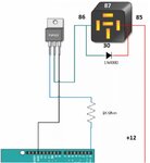
It uses an automotive 12v DC relay.
But to trigger it, there is a schematic enclosed that I have absolutely no idea how it works.
I believe an auto relay is wired as such
# 30 High load input
# 85 Switch
# 86 Switch
#87 High load out

If I use this example, do I bring the load power to pin # 30
and the load output power to pin # 87
I assume you attach the 1N4002 across the switch (relay coil)
Pin # 86 and pin # 85
And I have no idea what the TPI122, the 1N40002 or the 1K Ohm does
All I'm asking is that if I wire it as shown, can I just connect my input and output leads to # 30 and # 87"
I would greatly appreciate ANY and all responses to this post
Thank You very much
 

Attachments

  • Circuit.jpg
    Circuit.jpg
    243.1 KB · Views: 52

Re: HELP with some basic (I think) electronics

It should work but be careful to keep the wiring short, especially the one to GND on the Arduino.

It works like this:
The Arduino itself cannot provide enough switching power to drive the relay so it uses the transistor as a current booster. Think of the transistor as a simple on/off switch, when off it doesn't conduct so it looks like a switch in the 'off' position. When conducting it almost (not 100% efficient unfortunately) shorts out the middle and right pins (called 'collector' and 'emitter' pins respectively) so it looks like a switch in the 'on' position. Whether it conducts or not is decided by current flowing into the left pin which is called the 'base' connection. The Arduino either provides that current to turn the transistor switch on, or is doesn't provide it to turn the transistor off. The important point is the transistor itself needs very little current to operate it while still being able to switch quite a large current, easily enough to operate the relay.

The diode across the relay coil is important. I'm over simplifying things but think of a diode as a device that only conducts current in one direction. It is wired across the relay coil in a way that does NOT conduct during relay operation. This may seem pointless, it just sits there doing nothing but there is a good reason for it being there. A relay coil is basically lots of turns of wire around an iron core to make an electro-magnet. When current flows it creates a magnetic field that pulls the switch mechanism inside the relay and makes the contacts open or close but when the current is turned off, that magnetic field collapses rapidly and gets converted back to a voltage across the coil connections. The polarity of the voltage is the opposite of the voltage that created the field and the diode sees it in the direction it wants to conduct in. As it conducts, it protects the transistor from excessive voltage.

I would offer a word of caution: it will work just fine if your Arduino is powered from 5V but if you have one that runs on 3.3V you might have to drop the resistor value or else the transistor may not fully switch on. [for the tech minded - it's a Darlington type with Vbe of around 2.5V]

Brian.
 

Re: HELP with some basic (I think) electronics

the arduino puts out (essentially) an on off signal
+V (5V or 3.3V depending on supply) and 0 V (return to source)

this circuit will only run the motor in one direction

you will need to duplicate it to drive the motor the other way.
everything is duplicated except the arduino
the second relay gets connected to the motor in the opposite direction
the second 1k resistor has to go to a different pin on the arduino
 

Re: HELP with some basic (I think) electronics

Q1) Where is the ground wire from the Arduino Uno Ground to the car ground?
Q2) How are providing DC Power to the Arduino Uno ?
 

Re: HELP with some basic (I think) electronics

1. Yes, ground
2. Need to find a way to step down the 12v dc to I believe either 5v or 3.3v is what the input on the board shows.
Waiting to purchase the components until I am sure I got this wiring correct.
If I thinks it will work, I will immediately order all the parts require.
If this works it will because the wonderful responses from this site.
I REALLY appreciate you folks with the knowledge taking your personal time to dummies like me.
Thanks to you ALL!
Jerome
 

Re: HELP with some basic (I think) electronics

before you start buying, please draw a COMPLETE schematic of what you intend to build
and post it, with part numbers

show all the parts
show all the wires (specify the gauge you intend to use)
show the connections to the car / outside world

the more and better information you provide, the better the help
 

Re: HELP with some basic (I think) electronics

WOW.
I will need some time to do all of that.
I is started but I need to finish.
I will post it after I complete layout.
THANK YOU very much.
 

Status
Not open for further replies.

Similar threads

Part and Inventory Search

Welcome to EDABoard.com

Sponsor

Back
Top