Continue to Site

Welcome to EDAboard.com

Welcome to our site! EDAboard.com is an international Electronics Discussion Forum focused on EDA software, circuits, schematics, books, theory, papers, asic, pld, 8051, DSP, Network, RF, Analog Design, PCB, Service Manuals... and a whole lot more! To participate you need to register. Registration is free. Click here to register now.

[SOLVED] Operation of variable inductance

Status
Not open for further replies.

Zak28

Advanced Member level 2
Joined
Aug 19, 2016
Messages
579
Helped
6
Reputation
12
Reaction score
6
Trophy points
18
Activity points
4,681
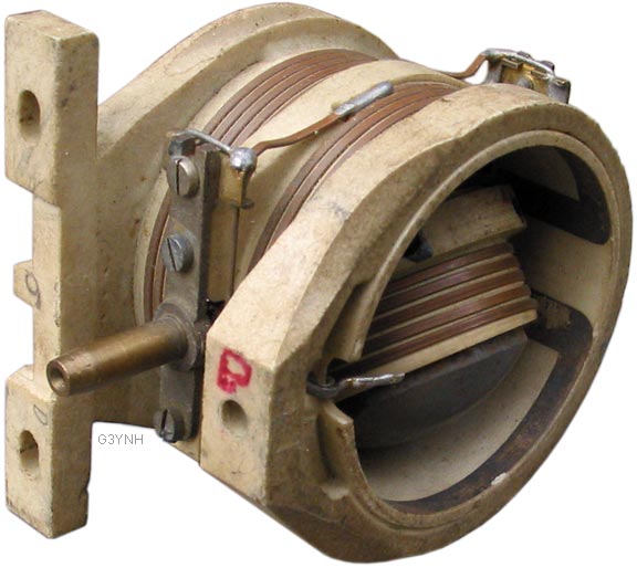
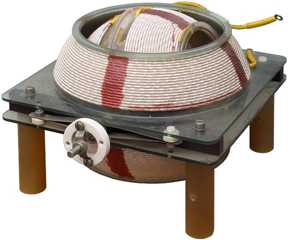
Do outer coils of these specialty tuning inductors loose inductance when axis of inner coil becomes normal to axis of outer coil and greatest when inline with axis of outer coil? Both inner and outer coils appear to be conducting making one single variable inductor.

FuG10.jpg


lfvario.jpg
 
Last edited:

Hi,

Imagine this:
If the inner and outer coils produce a magnetic field in the same direction, then the magnetic "fields" add and the overall inductance is high.
Now turn the one coil by 180° and the magnetic fields are in opposite direction...the fields subtract....resulting in low overall inductance.

Klaus
 
  • Like
Reactions: Zak28

    Zak28

    Points: 2
    Helpful Answer Positive Rating
Were these installed in old-fashioned radios? I've read how regenerative receivers were built for a while. They had an extra tuning knob attached to the variable inductors. A listener would dial in the station with the primary knob, then rotate the inductor knob, until he heard a sudden boost in volume which meant regeneration had kicked in.

Such radios made it necessary for the listener to adjust two knobs. I understand they started losing the popularity race, as manufacturers designed found better tuning circuits to make their radios more sensitive and more selective.
 
  • Like
Reactions: Zak28

    Zak28

    Points: 2
    Helpful Answer Positive Rating
Hi,

Imagine this:
If the inner and outer coils produce a magnetic field in the same direction, then the magnetic "fields" add and the overall inductance is high.
Now turn the one coil by 180° and the magnetic fields are in opposite direction...the fields subtract....resulting in low overall inductance.

Klaus

Wouldn't this be more than simple additive flux since its typically carrying high frequency ac and even at large currents? I suppose parasitics can detriment the operation of this tuner much akin to what happens in cavity resonators or other specialty oscillators.
 

Variometer tuning went out of fashion in the 1930s when it was realized variable capacitor tuning was far easier to implement. The top surface looks plastic and the insulation on the wires is PVC so these are clearly replicas.

They have nothing to do with regeneration, that came later when vacuum tubes became available to give enough gain for it to be possible, this was just for main tuning in crystal sets.

I have an original 'BBC' variometer tuned crystal set here - and it still works - but you need great patience to find a good spot to land the cats whisker on the Galena crystal (that's a diode to anyone under the age of 90!) to get a usable signal.

Brian.
 
the size of the wire etc in the photo's indicate they were likely used in low/med power transmitters intended to be used over a fairly wide band - 50 - 300W
 
  • Like
Reactions: Zak28

    Zak28

    Points: 2
    Helpful Answer Positive Rating
Variometer tuning went out of fashion in the 1930s when it was realized variable capacitor tuning was far easier to implement. The top surface looks plastic and the insulation on the wires is PVC so these are clearly replicas.

They have nothing to do with regeneration, that came later when vacuum tubes became available to give enough gain for it to be possible, this was just for main tuning in crystal sets.

I have an original 'BBC' variometer tuned crystal set here - and it still works - but you need great patience to find a good spot to land the cats whisker on the Galena crystal (that's a diode to anyone under the age of 90!) to get a usable signal.

Brian.

What do you suppose junction capacitance figures are for galena - whisker junction? Whiskers haven't gone away as we find them renamed bond wires in transistors and even still diodes are made with whiskers those of the point contact type. The bell labs transistor was a whisker also they just rename it to bond wires since they turned out to be very precisely placed. Fuses might have been called that also.
 

I have no idea and I would think it would be very hard to measure given their fragility. Modern 'whiskers' are metal bonded rather than point contact devices, they use a weld instead of pressure to make the connection. The problem with Galena point contact diodes is if you sneeze within a 10m radius their characteristics completely change!
20190607_092333a.jpg
They don't make them like that any more!
20190607_092304a.jpg
The complete "wireless set", the detector is on the right and under the tuning knob is the variometer.

Brian.
 

Status
Not open for further replies.

Similar threads

Part and Inventory Search

Welcome to EDABoard.com

Sponsor

Back
Top