Continue to Site

Welcome to EDAboard.com

Welcome to our site! EDAboard.com is an international Electronics Discussion Forum focused on EDA software, circuits, schematics, books, theory, papers, asic, pld, 8051, DSP, Network, RF, Analog Design, PCB, Service Manuals... and a whole lot more! To participate you need to register. Registration is free. Click here to register now.

simple proximity sensor, help needed

Status
Not open for further replies.
J

Javid.zare.s

Guest
hi everyone, I got free time and I want to build a circuit similar to the design of this site,
https://circuitdigest.com/electronic-circuits/ir-detector-circuit
as described in the website it detects and reacts with the presents of ir light
but what I need is exact opposite, it should detect and react with absence of iR light.
I'm not an expert, I just can assemble circuits , so please explain simple for me
thanks in advance!
 

To be useful your project ought not send an alert in total darkness even though IR is absent then. I think you want a circuit which has two detectors: (1) one for IR, and (2) one for visible light.

The circuit produces an alert when the general purpose detector sees light (at any visible wavelength), and the IR detector sends no signal.
 

    V

    Points: 2
    Helpful Answer Positive Rating
To be useful your project ought not send an alert in total darkness even though IR is absent then. I think you want a circuit which has two detectors: (1) one for IR, and (2) one for visible light.

The circuit produces an alert when the general purpose detector sees light (at any visible wavelength), and the IR detector sends no signal.

so this means it cannot be modified to perform my task?
 

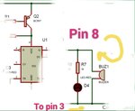
If all you want is the reversed operation of the existing circuit, simply lift the buzzer, R7 and LED (as connected) so their existing connect to pin 3 goes to pin 8 instead and their existing connections to ground goes to pin 3.

The circuit is a little odd, why they decided to switch the supply to the 555 instead of using the reset pin is strange. It can't be to save power because the IR emitter is always on anyway.

The circuit may still trigger in the presence of other light sources because the IR detector is not particularly selective, it can see more than just the light from the emitter LED. A far better and simpler method is to use the 555 as an oscillator then use it to drive the emitter LED. The detector can then be changed to a standard remote control receiver IC (TSOP series for example) which contains filter circuits to exclude unwanted signals.

Brian.
 

    V

    Points: 2
    Helpful Answer Positive Rating
If all you want is the reversed operation of the existing circuit, simply lift the buzzer, R7 and LED (as connected) so their existing connect to pin 3 goes to pin 8 instead and their existing connections to ground goes to pin 3.

The circuit is a little odd, why they decided to switch the supply to the 555 instead of using the reset pin is strange. It can't be to save power because the IR emitter is always on anyway.

The circuit may still trigger in the presence of other light sources because the IR detector is not particularly selective, it can see more than just the light from the emitter LED. A far better and simpler method is to use the 555 as an oscillator then use it to drive the emitter LED. The detector can then be changed to a standard remote control receiver IC (TSOP series for example) which contains filter circuits to exclude unwanted signals.

Brian.

tnx mr Brian!
so is this the right configuration?
IMG_20190606_013330_844.jpg

if this works I'll try to do something about ambient light as you said to.
my problem is pulling the trigger for now
 

That is correct.
Pin 8 is always high during operation. Pin 3 goes high when the IR beam is interrupted and otherwise is low. In the original circuit, current to the LED and buzzer flowed out of pin 3 to ground when it was high. In the new configuration current flows in to pin when it is low so the operation is reversed.

It is still better to use the reset pin on the NE555 but see how you get on with this modification before trying anything else.

Brian.
 

    V

    Points: 2
    Helpful Answer Positive Rating
Status
Not open for further replies.

Part and Inventory Search

Welcome to EDABoard.com

Sponsor

Back
Top