Continue to Site

Welcome to EDAboard.com

Welcome to our site! EDAboard.com is an international Electronics Discussion Forum focused on EDA software, circuits, schematics, books, theory, papers, asic, pld, 8051, DSP, Network, RF, Analog Design, PCB, Service Manuals... and a whole lot more! To participate you need to register. Registration is free. Click here to register now.

Charging an unloaded capacitor

Status
Not open for further replies.

miso156

Junior Member level 2
Joined
Jan 13, 2019
Messages
23
Helped
0
Reputation
0
Reaction score
0
Trophy points
1
Activity points
222
I am tying to charge a 4.7mF capacitor from a boost coverter, which is limited by very high resistance (100ohm) of its power supply. Anothe words, due to this the capacitor will be charged very slowly.


joule.png

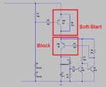
What happened is when the C1 voltage reaches Vmax after soft-start (charging via R3 initially), the capacitor voltage slowly falls to 1-2V, somethimes even converter stops oscilate, and then rise again to Vmax in 10s intervals.

I have a suspect, the energy from C1 flows back to converter and unload its output.
I would like to avoid to use another diode to isolate capacitor from whole circuit.
 

Hi,

It becomes discharged by R3-R4-D2-D3-GND

Klaus
 

Thaks for answear, I did a simulation, R3 remains shorted (no voltage on it) when capacitor is in discharging, i.e. when boost is not deliveriong energy to C. I have no idea if an unloading can cause so impact to kick converter from oscilation.

BTW, I am surprised when during discharging can flows so high reverse currents (according simulation).

AAAu.png
 

Hi,

What about trying an "active diode" between Q2 R3 and C1, then? MOSFET or BJT switch to block path when cap is charged, using a comparator to compare a voltage to a reference to turn the switch on and off?

Not sure why just using a diode is not of interest, it's a simple solution and only one part. I don't understand but it would be nice to know why - Why?
 

Thx, I don't like to put 2 schottky in series due to efficiency. The 1.5V power supply with 100ohm series deliver so less energy I would get at the output almost nothing.


To cut the charged Cap from supply is a good idea, do you mean something like add another switch or use the one from the soft start?

AAAAAAAAA.png
 

sorry, but i do not see a boost converter

i don't see the transistors as switches, as there seems to be no control signals
both transistors appear to always have some sort of base drive that may or may not vary

would you please show simulations and the control loop?


i don't see the second schematic as a boost converter either

i don't see the soft start doing anything except turning on when power is applied

please show the entire circuit and the simulations/measurements
 

Hi,

I wouldn't use a joule thief for what you're doing, afaik they are a poor-man's boost converters and not good for one component or other, don't remember which now, maybe especially the battery - you'd need to read up on that to make an informed choice of appropriate building block for your design goal. Many, many DCDC ICs out there that can do what you need, parametric searches on manufacturer's websites or suppliers will help to browse and choose one. DCDC not my area of expertise, I'm afraid, sorry.

What I meant was something like the circuit below which has a lot of design errors because I was rushing to show the general idea and I don't have the time to sit waiting for a very slow simulation to charge a large capacitor to ~1V, so don't copy it as is and expect it to work, however at 1.5V supply not sure what comparators are available. Home-made/Discrete low-voltage comparators are not so hard to make with BJTs but not sure that's what you'd want to explore for this circuit (maybe 10 to 20 more parts, depending on need for quality).
1.22V adjustable references are widely available and can be raised to 1.5V or divided down to 1V or whatever you need one way or another with two resistors.

Honestly, sometimes a little more reading can save a little more design and simulation time and making time in the long run, no offense intended.

cap charge thing very rough sketch as concept.JPG
 
Thank you, the purpose I am doing this is a battery charger for 3.7V Li-ion supplyed from very small solar panel. The charged 4m7 capacitor will be discharged to battery in 2 sec intervals.

If I calculate right, I can get from this small panel about P=1.5x1.5/100 = 0.0225W.
For this little power is probably better to use charge pump because I dont know the LC boost IC which can handle so small input power and be able to charge a 4m7.

For now, i did something similar with 5.5V panel, where is no need to use a converter:

Solar_pulse_charger.png

However, for 1.5V panels, I need to convert votage to about 4.5V and seems to me the best way is to let the 4m7 Cap charged (i.e. supplyed) until comes the discharging signal? Or is it necessary to block it from supply for such small thing like parasitic discharging? There must be some solution.
 

Hi,

Pardon my saying, better you than me: 1.5V and ~22mW... :)

Probably not a great circuit and certainly a relatively different idea to what you're doing, but for the sake of a picture speaks more than I can explain... Anyway, if you focus on the right-hand side (D2, R1, C3 and Rload), you can ignore T2 as far as I recollect - there's a diode to stop the capacitor leaking "backwards"...

ebike pmos approximation 2 schematic.JPG

Frankly, I have no idea but think it may well likely leak without a blocking device. You really need to use a Schottky do you? They leak loads compared to a bog-standard silicon diode.

What I was simulating last night looked like it would take several minutes to charge the 4.7mF capacitor, and that circuit had far more power at its disposal.

Charge pump or discrete voltage tripler sounds good. Home-brew/discrete voltage doublers are usually unwelcome for me as they have low output current capability (and rather inefficient) but it appears that maybe isn't an issue for you if it can charge the capacitor slowly.

This capacitor is for an MCU to finalise any tasks it was doing and shut down properly when the power goes or something like that? Just asking out of curiosity.

- - - Updated - - -

Looking at your latest schematic again, wouldn't the battery be better off on ground and swapping the NMOS low-side switch for a PMOS high-side switch? What am I misreading about the schematic/functionality, please?
 

If I calculate right, I can get from this small panel about P=1.5x1.5/100 = 0.0225W.
No. If it's actually a 1.5 V source with 100 ohm resistance, maximum power point is 0.75V/7.5mA or 5.5 mW. That's however an unrealistic solar cell model.
 

A capacitor-based voltage multiplier has an advantage over the inductor-based boost converter. With capacitors the output voltage can never rise above a certain limit. This reduces the risk of overcharging a battery. And when you remove the battery, output voltage does not rise alarmingly. (Whereas, a boost converter with no load can soar to a high voltage, destroying components.)

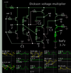
Thr Dickson voltage multiplier charges capacitors in parallel, then discharges them in series with the addition of the supply voltage. This simulation shows how a 1.5V supply is tripled so it can charge your 3.7v battery.
It does this with 2 capacitor stages in a combination of H-bridges (9 transistors total).

Dickson voltage multiplier 9 transis 1_5V supply charge 3_7v battery.png

The four leftmost transistors create an oscillator with C1. It clocks the right half of the circuit. C2 & C3 charge in parallel simultaneously in one direction. Then they discharge in series, sending current through the battery.

The 1 ohm resistors are unnecessary.

Values are selected so that the circuit draws upwards of 100 mA (in theory) assuming your PV cell provides that much power.
 

Status
Not open for further replies.

Similar threads

Part and Inventory Search

Welcome to EDABoard.com

Sponsor

Back
Top