Continue to Site

Welcome to EDAboard.com

Welcome to our site! EDAboard.com is an international Electronics Discussion Forum focused on EDA software, circuits, schematics, books, theory, papers, asic, pld, 8051, DSP, Network, RF, Analog Design, PCB, Service Manuals... and a whole lot more! To participate you need to register. Registration is free. Click here to register now.

How can I generate Sine wave from any periodic waveform that has low frequency?

Status
Not open for further replies.
Not lower than imposed by the Nyquist criterion. In practice at least 25 to 30 kHz, higher if you want to keep the filter effort low.

If I want a 10kHz sine wave, by Nyquist criteria, 25kHz to 30kHz should be my filter's cut-off frequency, right? It is not carrier frequency. I think Carrier frequency should be much higher, but I don't know how to choose the carrier frequency.
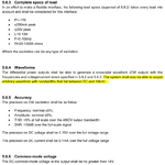
 

you specified a sin wav up tp 10 kHz, with THD < 5%

where does carrier frequency come in?
carrier frequency implies some sort of modulation.
is there any expected modulation?

The carrier frequency could come from Class D amplifier or Class C amplifier, and the power amplifier's gate driver signal comes from FPGA.
 

carrier frequency implies some sort of modulation.
Right. PWM can do, as said. See e.g. post #12.

- - - Updated - - -

If I want a 10kHz sine wave, by Nyquist criteria, 25kHz to 30kHz should be my filter's cut-off frequency, right? It is not carrier frequency.
It is in the first order. Nyquist criterion defines the ratio of signal to carrier frequency. The filter transition band however has to fit in-between.

That's easily achieved in the digital domain with audio filters. But an analog output filter for a class-D amplifier suggests larger ratios.

As I don't apply to design the application for you (I guess neither other Edaboard members), I suggest that you start to do calculations on your own.

the power amplifier's gate driver signal comes from FPGA.
Fine, this gives you the option to choose frequencies independent of controller restrictions, just according to power stage and filter properties. The initial request for using "lower switching frequency" doesn't seem substantiated under this prerequisite.
 

I do not know what is the objective of the said exercise, but you can always use a bandpass filter to get a sine wave from any arbitrary waveform.

Of course if you want to have a variable centre frequency, you have to do more work.

By the way, a square wave of frequency f (say 10kHz) will have sine wave components of f, 2f, 3f etc (but no sub-harmonics).

So if you want to have pure sine wave, you have to use a high order band pass filter. But using a digital filter may be simpler in many cases.

I think a square wave of frequency f (say 10kHz) will have sine wave components of f, 3f, 5f, 7f....Odd harmonics!
 

I have used a Switched Capacitor Butterworth Lowpass Filter IC to produce an audio sinewave with extremely low distortion (almost no harmonics)

Hi,

Can you please share some reference about what you have done (Switched Capacitor Butterworth Lowpass Filter IC)? BTW, what is your input signal?
 

The switched capacitor filter IC I used a long time ago is obsolete now and not made anymore. Maxim have some today.
 

Here is more specific requirements. Instead of arbitrary waveform output, I need only Sine wave.

Untitled.png
 

Filtering a square wave with a switched capacitor or other low power filter implies that you have an analog power amplifier to generate the specified output. In this case, it would be much easier to use an oversampling audio DAC as signal generator.

- - - Updated - - -

Doesn't change much for the hardware requirements. You want sine of arbitrary frequency, DAC is an universal hardware solution.
 

I think a square wave of frequency f (say 10kHz) will have sine wave components of f, 3f, 5f, 7f....Odd harmonics!

right, but...

A square wave of 50% duty cycle has some symmetry and because of that even components (even harmonics) disappear.

But if you have a pulse sequence that have 40% (something not equal to 1/2) duty cycle, the symmetry disappears. Then you will have all the frequencies.

A small deviation from the 50% symmetry can cause these even harmonics to appear.

You are right! 50% duty cycle square wave has odd harmonics, but other than 50% has all the frequencies. Thanks for correcting!
 

By definition a square wave has 50% duty cycle. Any other duty cycle wave would be called Pulse wave or rectangular wave.

Just saying.
 
you might consider a peaking butterworth low pass filter
Sallen Key style
set Q about 8 or 10, let R1 = R2 and C1 = C2,
one op-amp, 2 resistors, 2 capacitors and bypass capacitors

net result is your 10 kHz signal since the 10 kHz square wave input has no lower frequency components
 

Second order Butterworth has Q=0.71 and monotonous magnitude response by definition. Q=8 corresponds to Chebyshev with about 18 dB ripple.

In any case the solution is far from the original requested 0 - 10 kHz frequency range, but may be it's not so serious.
 

Status
Not open for further replies.

Similar threads

Part and Inventory Search

Welcome to EDABoard.com

Sponsor

Back
Top