Continue to Site

Welcome to EDAboard.com

Welcome to our site! EDAboard.com is an international Electronics Discussion Forum focused on EDA software, circuits, schematics, books, theory, papers, asic, pld, 8051, DSP, Network, RF, Analog Design, PCB, Service Manuals... and a whole lot more! To participate you need to register. Registration is free. Click here to register now.

Does RHP zero in boost/buck-boost always exist?

Status
Not open for further replies.
Ok you're right that I can see DCM modulation schemes that add or subtract to the time when the switch is turned on which have no RHPZ as you describe.

But I can see DCM modulation schemes that add or subtract to the time the switch is turned off which are discontinuous and have an RHPZ as I described.

So I see this depending on the implementation, not strictly on DCM vs CCM.
 

Um, not quite, if you are in true DCM - not boundary mode - then there is no delayed action type RHP zero - regardless as to whether you view it as constant off time or constant on time. In constant ON time there is a limit to which you can reduce the off time and still be in DCM, in constant OFF time there is a limit to which you can increase the ON time and still be in DCM. As long as you are in true DCM there is no delayed action RHP zero - only the normal zero that occurs due to the series inductance ...
 

Here is my point that both scenarios can exist in DCM.

Boost schematic
DCM Boost Sch.PNG

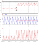
With the above schematic the modulator changes when the switch turns off and there is a RHPZ (circled).
DCM Boost RHPZ.PNG

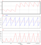
With the gate drive (and control reference) inverted the modulator varies when the switch turns on and there is no RHPZ.
DCM Boost NO RHPZ.PNG
 

Certain texts refer to DCM and CCM as "complete energy transfer mode" and "incomplete energy transfer mode" respectively, and this is one case where such a description is useful. In DCM, energy is taken from the input and stored in the inductor during the switch ON time. During the OFF time, all of that energy is delivered to the output. Thus, when averaging over a switching period, there's no delay in energy transfer. In CCM, only a fraction of the inductor's stored energy is delivered to the load each switching period. It's this partial energy transfer that permits the RHPZ to manifest in boost and buckboost converters.

Now, if we want to look at things in more detail, we can observe that in DCM, increasing the duty cycle does delay the transfer of energy to the output (since the ON time has been increased), though by only a fraction of a switching period. The standard formulation of state space averaging does not account for when something happens within a switching period. I believe the paper cited in TI's app note is trying to "fix" this. However this sort of behavior is much more complicated than a RHPZ.

edit: and I think this is exactly what is shown in asdf44's waveforms above. It quacks like a duck, but I don't think it's a duck.
 

apologies, but the timing of the step in the graphs is of import - even so the poorly behaved one has higher power o/p within one cyc

- - - Updated - - -

if you shift the step in the top one - left by a half cycle - you may well get the same result - as the lower set of graphs ...
 

Agree it hits a higher power operating point within one cycle...we're talking about a RHPZ that's above the switching frequency, so that's what we expect.

Shifting waveforms around could cause a double trigger in an extreme case or split the step response across multiple cycles. Regardless, positive steps work by delaying the point where power is delivered and that causes the RHPZ. Mtwieg described this perfectly as well (though Mtwieg, if it looks like a duck...)

I agree this is largely irrelevant since the feedback loop should already be steering well clear of the switching frequency, but its there none-the-less.
 

Above half the switching frequency, the PWM modulator starts showing significant time-varying behavior (as you noted, varying the delay of the input step causes the output response to change in shape, as opposed to simply shifting by the same delay). At that point, the system can't be described with a simple transfer function (in fact this is where the type of PWM modulator used starts to affect the results). In a way it may remind you of a RHPZ, but it's much messier than that in reality.
 
thank you mtwieg.

- - - Updated - - -

shifting the step of the upper set of graphs left by 1/2 a cycle will be instructive. It will not cause double pulsing in this case ( impossible) but will give a similar result to the lower set of graphs, even more instructive is to spread the step over 5 cycles - then the non-RHP zero response will be clearly seen.

As mtwieg says, or implies, doing things inside a complete cycle, cannot be described by the formulae often used.

What has been shown is that the output goes up inside a cycle - perhaps not as robustly as a buck derived converter - but none the less - what happens for commanded steps inside a cycle is not quite so relevant - as this would not usually be a ckt requirement.
 

Status
Not open for further replies.

Similar threads

Part and Inventory Search

Welcome to EDABoard.com

Sponsor

Back
Top