Continue to Site

Welcome to EDAboard.com

Welcome to our site! EDAboard.com is an international Electronics Discussion Forum focused on EDA software, circuits, schematics, books, theory, papers, asic, pld, 8051, DSP, Network, RF, Analog Design, PCB, Service Manuals... and a whole lot more! To participate you need to register. Registration is free. Click here to register now.

Fully differential continuous time integrator

Status
Not open for further replies.

Shady Ahmed

Member level 5
Joined
Jan 26, 2013
Messages
86
Helped
2
Reputation
4
Reaction score
2
Trophy points
1,288
Activity points
2,042
Hello, I am designing an integrator of a continuous time sigma delta ADC using a fully differential amplifier on cadence with input freq 1.5MHz and sampling freq at the comparator 256MHz.
In the integrator we add resistance parallel to the cap to adjust the dc ,but it gives a dc gain (R2/R1) with a corner freq 1/(2(pi)R2*c) so what should be the range of the dc gain and the ratio between the corner freq and the i/p signal frequency to insure that it is operating in the integrating range after the corner frequency?
 

In the integrator we add resistance parallel to the cap to adjust the dc
No, you don't if you want a true integrator. Adding parallel R creates a lossy integrator respectively first order low pass.

The "DC" of an integrator must be adjusted by negative feedback in the outer loop.
 

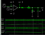
Does this setup resemble yours? PWM is fed to a DCR integrator, so it is smoothed to a volt level in the range 0 to 5v. Duty cycle ranges from maximum to minimum. Output voltage is in a linear (or roughly linear) relationship to duty cycle.

PWM 1_5 MHz 12v duty cycle max to min DCR integrator .png

RC values were adjusted so that the output waveform 'looks right'. The capacitor value is chosen so it discharges just slightly during idle gaps.

A parallel resistor is needed because without it the capacitor would maintain output voltage near 12V with hardly any drop. The parallel resistor value is chosen to create linear response of output V to duty cycle.

Originally 5v was the amplitude of pulses from the op amp. This resulted in 1.8v output voltage for 99% duty cycle. That was after much experimenting with RC values. Apparently some attenuation makes for better linear response.
Thus the incoming amplitude had to be raised so as to achieve an output range of 0 to 5v.
 

Status
Not open for further replies.

Similar threads

Part and Inventory Search

Welcome to EDABoard.com

Sponsor

Back
Top