Continue to Site

Welcome to EDAboard.com

Welcome to our site! EDAboard.com is an international Electronics Discussion Forum focused on EDA software, circuits, schematics, books, theory, papers, asic, pld, 8051, DSP, Network, RF, Analog Design, PCB, Service Manuals... and a whole lot more! To participate you need to register. Registration is free. Click here to register now.

[SOLVED] Feedback SMPS; Transfer function for error amplifier with series RC to GND connection

Status
Not open for further replies.

al3ko

Junior Member level 3
Joined
Apr 2, 2011
Messages
25
Helped
2
Reputation
4
Reaction score
2
Trophy points
1,283
Activity points
1,528
Dear all

I came across an error amplifier constellation as shown in Figure 1 in the attached graphic. Note how R1/C1 in the local OP-amp feedback is connected to GND. I am more familiar with the more commonly used structure as in Figure 2 in the attached graphic, where R1/C1 is in parallel to the capacitor C2 in the local feedback path. For Figure 2, I can comfortably derive the transfer function.

The goal is to obtain the transfer function Vopamp(s)/Vout(s) of the error amplifier as in Figure 1 in order to properly set the gains of the compensator to stabilize the system. Unfortunately, I am struggeling with it since I am not sure how to account for the GND connection.

Does anyone in this group have an idea on how to deal with R1/C1 when connected to GND when it comes to deriving the transfer function of the error amplifier?

PS:
I am not asking for you to do my job; I would be happy to derive the transfer function on my own, though I would need a little help in the beginning as I don't know how to cope with the R1/C1-GND constellation.

Thank you.
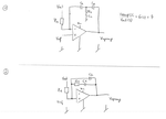
error_amp.png
 

figure 1 hasn't got resistive feedback to ensure the operating point. do you want an integrator or an amplifier here? because it is not an amplifier.
figure 2 has positive feedback, inverting input is nowhere, and hasn't got resistive feedback either, draw it again please.
 

figure 1 hasn't got resistive feedback to ensure the operating point. do you want an integrator or an amplifier here? because it is not an amplifier.
figure 2 has positive feedback, inverting input is nowhere, and hasn't got resistive feedback either, draw it again please.

Excellent catch, frankrose. I did a mistake in Figure 2 of my drawing. Please have a look at the revised drawing shown below. I also added resistor R2 into the figures for the sake of completeness, although AFAIK resistor R2 does not affect the transfer function. Let me ask you, frankrose, is there a fundamental difference between an error amplifier and an integrator? It is likely that I am using the wrong words in the wrong context here, but I am looking for a Type 2 or Type 3 compensator that acts to attenuate the error of a closed loop controlled SMPS. I apologize if my choice of words caused confusion. I hope that my intention is more clear now.

error_amp_1.png

The revised figures are now correct, and the goal is to obtain Vopamp(s)/Vout(s) of figure 1.
 

Yes, there is a difference, because amplifier has different relationship between its terminals. But as I see in google at the SMPS it is not a case, lot of paper calls above compensator circuit as error amplifier, so I also learnt something today.
Anyway, to get the transfer function maybe a good help the TINA or the SapWin softwares. Last is freeware symbolic analyser tool, I have never used it, google for it.

I am curious to hear about your opinion on the differences between an integrator and an amplifier, as you pointed out in your first reply:
figure 1 hasn't got resistive feedback to ensure the operating point. do you want an integrator or an amplifier here? because it is not an amplifier.
If you don't mind, would you please elaborate on this topic?

Thank you,
 

An inverting amplifier (which is also an error amplifier, with ground reference) has a transfer function: H(s)=-Rf/Rin, where Rf is the feedback resistor, and H(s) is independent from s, the complex frequency. https://en.wikipedia.org/wiki/Operational_amplifier_applications#Inverting_amplifier

An integrator's transfer function is: H(s)=-1/(s*R*C), where C is the feedback capacitance, H(s) here is depending on s, so you can see it is totally else.

Integrator is always used in bigger feedback systems because hard to set otherwise an operating point for the OPAmp. A simply way is the lossy integrator, where a resistor is added in paralel with the capacitance, basically a low-pass filter.
https://www.electronics-tutorials.ws/opamp/opamp_6.html
 

An inverting amplifier (which is also an error amplifier, with ground reference) has a transfer function: H(s)=-Rf/Rin, where Rf is the feedback resistor, and H(s) is independent from s, the complex frequency. https://en.wikipedia.org/wiki/Operational_amplifier_applications#Inverting_amplifier

An integrator's transfer function is: H(s)=-1/(s*R*C), where C is the feedback capacitance, H(s) here is depending on s, so you can see it is totally else.
Excellent - now I get your point. Thank you.

Then let me ask you in a slightly different way, having only resistors in the circuit. How would you obtain the transfer function in the below shown figure, when R3 is now connected to GND? Any guess?

Thank you,

opamp.jpeg
 

If the potential, or voltage between the 3 resistors is phi1, these equations are true:
a. Vin/Rin = I_R1
b. I_R1 = phi1/R3 + (phi1 - Vopamp)/R2
c. I_R1 = -phi1/R1

From c.: phi1 = -I_R1 * R1
Place phi1 to b.: I_R1 = -I_R1*(R1/R3) -I_R1*(R1/R2) -Vopamp/R2
Rearrange last equation: I_R1*(1 + (R1/R3) + (R1/R2)) = -Vopamp/R2
Express I_R1 from last equation: I_R1 = -Vopamp/(R2 * (1 + (R1/R3) + (R1/R2)))
Use a. on the left side of the last equation: Vin/Rin = -Vopamp/(R2 * (1 + (R1/R3) + (R1/R2)))
Rearrange: Vopamp/Vin = - (R2 + (R1*R2/R3) + R1)/Rin

You can see, if R3 is infinite, the gain equals with the non-inverting amplifier's gain exactly, where Rf = R1 + R2 in above case.
 

Hi frankrose,
thank you very much. In fact, I managed to obtain the same results today. Now, replacing some of the resistors with the capacitors and the RC series connection towards GND, I can then obtain the transfer function. It requires a bit of algebra, but should be doable. Let's see how the bode plots differ from each other.

Thanks a lot for your help - much appreciated. :thumbsup:

Cheers,
 

Status
Not open for further replies.

Similar threads

Part and Inventory Search

Welcome to EDABoard.com

Sponsor

Back
Top