Continue to Site

Welcome to EDAboard.com

Welcome to our site! EDAboard.com is an international Electronics Discussion Forum focused on EDA software, circuits, schematics, books, theory, papers, asic, pld, 8051, DSP, Network, RF, Analog Design, PCB, Service Manuals... and a whole lot more! To participate you need to register. Registration is free. Click here to register now.

UART-->RS485 (transmission is finished and it may respond)

Status
Not open for further replies.

intiCA

Junior Member level 2
Joined
May 9, 2019
Messages
23
Helped
0
Reputation
0
Reaction score
0
Trophy points
1
Activity points
188
Hello everyone,
hope right branch I've chosen.

UART --> RS485 interface:
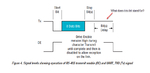
Could anyone explain me which way the slave knows that transmission is finished and it may respond to the Master?

BR
 

The Master should be ready to receive after it sends the last byte to the slave

Low-latency industrial RS-485 Communications ..
**broken link removed**
 
  • Like
Reactions: intiCA

    intiCA

    Points: 2
    Helpful Answer Positive Rating
ОК,
What does this bit stand for? Could you tell me?
 

Attachments

  • Signal_levels.png
    Signal_levels.png
    55.9 KB · Views: 189
Last edited:

Hi,

In my eyes this has nothing to to with RS485 (as physical interface), it should be defined by the protocol.
Which is unknown by now.

Klaus
 

Regarding DE deassertion delay, there's normally no reason to extend the driver enable beyond the stop bit, presumed the RS-485 lines are pulled to idle level by bias resistors.
 

ОК,
What does this bit stand for? Could you tell me?

On some hardware, detecting exactly when the last bit of the last byte is finally shifted-out the port, may be difficult to know.
DE must go LOW, after the last BIT of the last BYTE is shifted-out.
The "Transmit Buffer Empty" Flag might be SET when the Last Byte is initially sent to the Shift-Out Register.
So then the software needs to DELAY as that byte is shifted out, PLUS a 1 or 2 "Bit Time" delay before changing DE to LOW.
 
  • Like
Reactions: intiCA

    intiCA

    Points: 2
    Helpful Answer Positive Rating
Settling time for the idle condition is all I can think of. The protocol shouldn't matter as the device is only a driver, the output should follow the input. I wonder if the producer of the diagram was thinking of the time to empty a UART shift register rather than the interface itself.

Brian.
 

  • Like
Reactions: intiCA

    intiCA

    Points: 2
    Helpful Answer Positive Rating
Re: UART-->RS485 (transmission is finished and it may respond)

The "Transmit Buffer Empty" Flag might be SET when the Last Byte is initially sent to the Shift-Out Register.
So then the software needs to DELAY as that byte is shifted out, PLUS a 1 or 2 "Bit Time" delay before changing DE to LOW.
That may be true for a software implementation if you have difficulties to determine the exact frame end, but what should be the purpose of delaying DE? UARTs with built-in RS485 flow control usually don't delay the transmit enable beyond the stop bit, they however may assert DE before the start bit, FT232 e.g. does.
Note that the TXDEN is activated 1 bit period before the start bit. TXDEN is deactivated at the same time
as the stop bit.

- - - Updated - - -

PIC 24/32 UART is generating a transmitter idle status bit (TRMT) which becomes valid after the stop bit. Hardware transmitter enable is operated according to TRMT, without additional delay.
 

Re: UART-->RS485 (transmission is finished and it may respond)

Hello everyone,

Roughly, it may say that getting of distorted, unreadable Chars, as a variant of course, is a result of some kind of cutting, either it is start bit or stop bit, while transmission phase. Worse yet, it may be both cutted.

You know, both devices don't have any settings regarding mentioned above delaying. I can just imagine an answer of both manufactures regarding their firmware... "Our firmware is ok, it was tested!"

As far as I understand the delaying bits can be implemented via firmware changing only.

BR
 
Last edited:

Roughly, it may say that getting of distorted, unreadable Chars, as a variant of course, is a result of some kind of cutting, either it is start bit or stop bit, while transmission phase. Worse yet, it may be both cutted.

You know, both devices don't have any settings regarding mentioned above delaying. I can just imagine an answer of both manufactures regarding their firmware... "Our firmware is ok, it was tested!"
Useless considerations without referring to the protocol used by the devices, I think.

Are you reporting a specific problem? If so, please mention the relevant details.

If you are discussing the topic generally, please notice that half duplex communication can't work without a protocol followed by all involved devices. Industrial protocols like MODBUS have strict specifications of transmission timing, they can be implemented and verified straightforward.

I'm afraid, you are wrong. Many industrial devices communicate with each other and they are even not aware, that there are protocols at all, especially industrial.

Firmware --> UART-->RS485.

Well,
the Master is set to so-called 'transparent' protocol. Have you ever heard about this protocol? I'm almost sure -not. Also I'm almost sure you'll never find any volueable information on this protocol. If you will. I would be much appreciated.
The slave works on the sheme Firmware --> UART-->RS485.

BR
 

Re: UART-->RS485 (transmission is finished and it may respond)

That may be true for a software implementation if you have difficulties to determine the exact frame end, but what should be the purpose of delaying DE? UARTs with built-in RS485 flow control usually don't delay the transmit enable beyond the stop bit, they however may assert DE before the start bit, FT232 e.g. does.


- - - Updated - - -

PIC 24/32 UART is generating a transmitter idle status bit (TRMT) which becomes valid after the stop bit. Hardware transmitter enable is operated according to TRMT, without additional delay.

I do not see where member intiCA stated a PIC 24/32 was being used?

But if true, then per the PIC32 UART manual, section 21 & page 31 ...
Their example RS-485 Circuit suggests using the RS-232 RTS / CTS lines to control the RS-485 TX-Enable & RX-Enable hardware lines.
RTS & CTS are controlled by Software, which surely has execution delays.

You suggest using the TRMT flag ...
But "TRMT" is just a Status Bit in a Read-Only Register for the RS-232 UART that must POLLED by Software, again execution delays.
So, how can the TRMT ... a read-only status bit .. control the RS-485 TX-Enable & RX-Enable Hardware lines?

- - - Updated - - -

Hello everyone,

Roughly, it may say that getting of distorted, unreadable Chars, as a variant of course, is a result of some kind of cutting, either it is start bit or stop bit, while transmission phase. Worse yet, it may be both cutted.

You know, both devices don't have any settings regarding mentioned above delaying. I can just imagine an answer of both manufactures regarding their firmware... "Our firmware is ok, it was tested!"

As far as I understand the delaying bits can be implemented via firmware changing only.

BR

You may need to get a Digital Scope and/or a Digital Analyzer connected to the RS-485 line to determine the root cause of this problem.
What hardware are you using?
What Software Protocol are you using?

- - - Updated - - -

Did the RS-485 communications ever work properly, or is this a new install?

- - - Updated - - -

When does the bad comm happen?

a) When the Master sends a message to the Slave?
b) When the Slave replies to the Master?
c) Both ways ?

Do any packets get sent & received without comm errors ?
 
Last edited:
  • Like
Reactions: intiCA

    intiCA

    Points: 2
    Helpful Answer Positive Rating
Standalone RS232 to RS485 converters can't know where the end of the stop bit is, because the baudrate is unknown.
One solution I have seen is to only activate the driver for level '0' and for '0' to '1' transitions. The driver is disabled a short time after a '0' to '1' transition, shorter than the shortest possible time for one bit.
There must be resistors that guarantee the '1' state when no driver is active on the bus, but that is normally a good idea anyway.
With such standalone converters, the DE (driver enable) signal is handled automatically, no software control is necessary.
 
  • Like
Reactions: intiCA

    intiCA

    Points: 2
    Helpful Answer Positive Rating
Re: UART-->RS485 (transmission is finished and it may respond)

You may need to get a Digital Scope and/or a Digital Analyzer connected to the RS-485 line to determine the root cause of this problem.
What hardware are you using?
What Software Protocol are you using?

Bingo! You are right. I think I have to purchase an oscilloscope (it is final straw).:)

Did the RS-485 communications ever work properly, or is this a new install?
This is a new install. Consider that as an experiment within a project.

When does the bad comm happen?

a) When the Master sends a message to the Slave?
b) When the Slave replies to the Master?
c) Both ways ?
Do any packets get sent & received without comm errors ?

Well,
Half-Duplex variant.
the green one is received very seldom;
the orange one is received almost constantly. And always the same unreadable chars there are.
What else... I think, that all commands are being transmitted by Master very well. Because I observe always the same picture - adequate answers from the slave. True, they are mostly 'orange'.

Adequate -means correct number of Chars, e.g. the command 'A' implies 4 Chars in respective answer (as it's shown), the command 'Z' implies 9 Chars in respective answer, etc.
Moreover, sometimes I see 'green' one.


BR
 

Attachments

  • chart.png
    chart.png
    8.9 KB · Views: 100
Last edited:

Hi,

I'm afraid, you are wrong. Many industrial devices communicate with each other and they are even not aware, that there are protocols at all, especially industrial.
I´m designing industrial electronics and this statement can only be true on (propritary) full duplex peer to peer communications.

All I´ve done so far was with a known protocol where all the communication is specified.

This leads me to some questions:
* are we talking about 2 pair (full duplex) or 1 pair (half duplex) interface?
* is it a peer to peer interface or a true (multiple salves) bus?

Standalone RS232 to RS485 converters can't know where the end of the stop bit is, because the baudrate is unknown.
The circuits I´ve seen use the RS232 control lines (usually RTS) to enable/disable the RS485 transmitter.

Klaus
 

Hi,


I´m designing industrial electronics and this statement can only be true on (propritary) full duplex peer to peer communications.

All I´ve done so far was with a known protocol where all the communication is specified.

As I wrote above, the Master is set to so-called 'transparent' protocol. The Slave doesn't know any known industrial protocols like Modbus, etc.
The slave just executes commands which are programmed in its firmware.


This leads me to some questions:
* are we talking about 2 pair (full duplex) or 1 pair (half duplex) interface?
* is it a peer to peer interface or a true (multiple salves) bus?

RS485 half-duplex

Master's hardware is unknown, the Slave uses MAX485.
Still it's used Master and one slave. It's planned to hang on the bus up to five slaves.

The circuits I´ve seen use the RS232 control lines (usually RTS) to enable/disable the RS485 transmitter.

I did some study on slave's PCB and can definetely say that DE and RE are connected together.

Klaus

BR
 
Last edited:

Hi,

The slave just executes commands which are programmed in its firmware.
This is a protocol.
Without protocol it can't recognize commands..

Klaus
 

The circuits I´ve seen use the RS232 control lines (usually RTS) to enable/disable the RS485 transmitter.

I have two different types of standalone RS232-RS485 converters here that require no control signal, the driver is enabled/disabled automatically. There is no baudrate setting, and no specified "idle" time before another node can transmit.
I don't have any schematic, so I can't tell all details of the designs.
 

Status
Not open for further replies.

Similar threads

Part and Inventory Search

Welcome to EDABoard.com

Sponsor

Back
Top