T
treez
Guest
Hi,
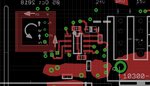
The attached is a printed antenna on a 4 layer PCB. (The grid lines are 1mm lines) It uses all four layers of the PCB to increase the turns. It is connected to an ST25DV04K-IER6S3 IC which reads signal received by this antenna.
Due to tolerances in the PCB manufacture, the thickness of the 0.15mm turns will have a tolerance, and so we need to measure the inductance of the sample one that we have. We believe the best way for us to do this is to solder a known C0G capacitor to its terminals and switch a DC voltage on to it, and then read the ringing frequency on a scope….then calculate inductance via w^2 = 1/(LC).
{obviously doing this with an unpopulated PCB…….just the resonant (test) capacitor soldered on.}
Do you believe that this is the best way?
We suspect that a large range of inductance values would actually still allow it to work, but thought we better check because the PCB manufacturer came back to us and offered to measure its inductance…because they said there would be a manuafacturing tolerance in the induictance.
ST25DV04K-IER6S3
https://www.st.com/resource/en/datasheet/st25dv04k.pdf