Eres_89
Member level 1
Hi All,
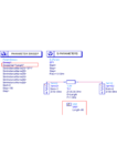
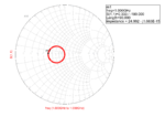
I've simple question related to the transmission line theory. Let we say, that we have such line which has Z0=35.35Ω, with electrical length equal to 90°, and it's terminated by the ports of 50 Ω. I'm wondering why in AWR simulator input and output impedances of the TL are equal to 25 Ω. According to quarter wave equation, I should obseve value of 35.35 Ω (when Zin = Zout).

Best Regards,
E.
I've simple question related to the transmission line theory. Let we say, that we have such line which has Z0=35.35Ω, with electrical length equal to 90°, and it's terminated by the ports of 50 Ω. I'm wondering why in AWR simulator input and output impedances of the TL are equal to 25 Ω. According to quarter wave equation, I should obseve value of 35.35 Ω (when Zin = Zout).

Best Regards,
E.

