Continue to Site

Welcome to EDAboard.com

Welcome to our site! EDAboard.com is an international Electronics Discussion Forum focused on EDA software, circuits, schematics, books, theory, papers, asic, pld, 8051, DSP, Network, RF, Analog Design, PCB, Service Manuals... and a whole lot more! To participate you need to register. Registration is free. Click here to register now.

Bi Directional Switch (Does it shorts ?)

Status
Not open for further replies.

Antor

Member level 2
Joined
Mar 1, 2019
Messages
51
Helped
0
Reputation
0
Reaction score
0
Trophy points
6
Activity points
501
01f05.jpg


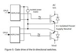
The file attached shows a bidirectional switch built with IGBT and optocoupler gate drivers from a paper Click here for article (It's open to public)

Isolated power supply neutral connected to IGBT common emitter node.

My question is : When Vin(AC) positive alternance is happening and switch above is triggered, does it make a short circuit to X point ?
 

The gate driver is referenced to the (S) of both and when it turns on it drives a positive Vgs to both fets. Thus they're both on and free to conduct.

When the gate driver is off one fet's body diode will conduct, thus meaning it has near 0 volts across it while the other fet will block the entire voltage.
 
  • Like
Reactions: Antor

    Antor

    Points: 2
    Helpful Answer Positive Rating
The reverse diode in parallel to each switching device is intended to prevent a reverse voltage that could burn each of them when in the negative cycle of the AC input.
 
  • Like
Reactions: Antor

    Antor

    Points: 2
    Helpful Answer Positive Rating
question.png

I guess I couldn't express myself because of my poor english skill.

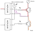
Vdc sourcing the optocouplers is an isolated (some calls it floating) power supply. But it's - (neutral) is connected to common emitter node.

If switch 1 is triggered which path current follows ? Orange ? As it intended or Purple (not intended)

Is there any chance of AC makes short circuit to DC's neutral ?
 

You seem to have difficulties to grasp the concept of an isolated power supply.

Sure the "DC neutral" is shorted to the "X" node respectively the in- and output node in switch on state. But due to isolation, no current flows through the "purple" path. The DC neutral node voltage simply follows the X node.

DC/DC converter and opto coupler have however a certain common mode capacitance. An AC voltage across the isolation causes a reactive current through the capacitances. It's also required that DC/DC converter and opto coupler have sufficient isolation rating and undergo respective high pot tests.

Why do you have separate gate drivers for positive and negative switch? For a basic bidirectional switch, one driver can drive both gates.
 
  • Like
Reactions: Antor

    Antor

    Points: 2
    Helpful Answer Positive Rating
Thanks for answers. That's a big relief for me because I already ordered my pcb and it takes 1 month to receive.

Why do you have separate gate drivers for positive and negative switch? For a basic bidirectional switch, one driver can drive both gates.

question2.JPG

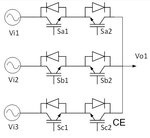
Goal is to synthesizing an AC output at desired V/f, directly from 3-phase using Bidirectional Switches (BDS).
When commutating output from one input to another I have 2 options.
1 - death time (I don't want load phases open-circuit not for a moment, so this is not an option)
2 - safe commutation
I need to do 4-step safe commutation to accomplish a safe commutation. To accomplish this I must be able to control switches seperately.

4-Step commutation

question3.JPG

Chart and tables explaination :
i>0 means current flows from source to load,
i<0 means current flows from load to source.

As an example current switching state is Saa (output connected to input A)
Next we need to disconnect Saa and connect to Sbb (output needs connected to input B)
First we need to make switching S1 S2 S5 and Sbb to accomplish this (4-step)

Mathematical simulation results promising but I want to see hardware implemented results. That's why I'm around.

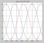
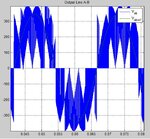
question5.JPGquestion4.JPG
Figure on the left is current, one on the right is Line-Line voltage

Edit Reason : Typo
 

Thanks for the explanation. I agree that separate switch control may be advantageous in this application. As you have three IGBT midpoints, you need three separate isolated DC supplies in this case.
 
  • Like
Reactions: Antor

    Antor

    Points: 2
    Helpful Answer Positive Rating
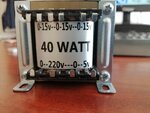
40w15x3p5v.jpg
I got this transformer and hoping to supply demand.
 

Status
Not open for further replies.

Part and Inventory Search

Welcome to EDABoard.com

Sponsor

Back
Top