Continue to Site

Welcome to EDAboard.com

Welcome to our site! EDAboard.com is an international Electronics Discussion Forum focused on EDA software, circuits, schematics, books, theory, papers, asic, pld, 8051, DSP, Network, RF, Analog Design, PCB, Service Manuals... and a whole lot more! To participate you need to register. Registration is free. Click here to register now.

Mains setpoint monitoring basic circuit: best choice.

Status
Not open for further replies.
Addendum:
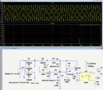
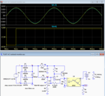
In my simulation the yellow traces are the 220Vac simulation results and the blue traces are the 210Vac simulation results.
 

...
Note that this circuit detects the peak AC voltage.
To detect the true RMS would require the addition of a true RMS conversion IC.

View attachment 152815

By detecting the peak here, you mean the instantaneous amplitude or you mean the peak of the mains voltage? The overall rectified waveform is averaged out by the bulk capacitor leaving some ripple that's related to its capacitance. The larger the capacitance, the closer all points on the filtered waveform gets to ((Vac*1.414)-Vd)*2/pi

- - - Updated - - -

With the magnitude of current required by this 'mains monitor' I expect capacitance of less than 200uF to reduce the ripple to less than +-1V or so.
 
Last edited:

Hi,

This means peak value measurement.
It is even less precise than your previous method, because it takes only a very short time of the fullwave into account. All the rest of the time the signal is ignored.
I don't think it's peak because of the filter capacitor after the diode bridge. This capacitor tends to average the rectified dc pulses.
It seems you mix accuracy and precision.
If you don't need accuracy but precision to be within +/-2% for a small area around the setpoint...then this eases design.
...
Use excel to do a simple simulation:
Let's use a sine with 10% third overtone.
V(t)= sin(t) + 0.1 × sin(3 × t + phi)
Phi is phase shift.
RMS calculation gives a constant value independent of phi.
Every other method will vary the output value depending on phi...even if the amplitude of both sine is constant...
Klaus
Yes, I guess I may have mixed up precision and accuracy but I can't affect accuracy very much in this case since that would depend on how much the actual mains waveform differs from the ideal sine wave and how much harmonics is present on the power line at any particular time.

- - - Updated - - -

Hi,

You say "some"... Must ask: Is wide-ranging hysteresis (between VthL and VthH) possible with the part or does it seem to have a somewhat limited/restrictive range?

Based on the simulation, it seems to be restricted because the shape of the hysteresis curve began to change significantly at some point as I increased demand for wider hysteresis. The change was so significant that I didn't like what I saw.

- - - Updated - - -

...
The larger the capacitance, the closer all points on the filtered waveform gets to ((Vac*1.414) - Vd)*2/pi
...

Correction: ((Vac*1.414) - 2*Vd)*2/pi
 
  • Like
Reactions: d123

    d123

    Points: 2
    Helpful Answer Positive Rating
I don't think it's peak because of the filter capacitor after the diode bridge. This capacitor tends to average the rectified dc pulses.
The larger the capacitance, the closer all points on the filtered waveform gets to ((Vac*1.414)-Vd)*2/pi

The statements apply to an averaging circuit, not the circuit in post #15. No averaging circuit has been yet posted in this thread.

- - - Updated - - -

To make an averaging circuit, you'll put a load resistor after the rectifier and a filter resistor before the capacitor, Rfilt >> Rload.
 
Hi,

I agree with FvM

@OP: There are simple free simulation tools. Use them.

Klaus


I just ran simulation of crutschow's circuit on LTspice. After the bridge rectifier, the average and the RMS values of the voltage equals the peak.

I was wrong with averaging it as if I was averaging a sine wave.

Now that LTspice is reporting Vpk = Vrms = Vavg, we can just use the Vdc = ((Vac*1.414) - 2*Vd) relationship.

I hope that would be able to do the job. I'll just have to tune the TL431 reference voltage divider resistors to obtain my setpoint.
 
Last edited:

I noticed that the current through the optocoupler LED is less than 2mA. Please, over time, how will CTR degradation affect the performance of the opto?
 

I noticed that the current through the optocoupler LED is less than 2mA. Please, over time, how will CTR degradation affect the performance of the opto?
The current transfer ratio may drop, but at that low current it's unlikely to degrade significantly.
You just drive the LED so that any CTR reduction will not keep the output from switching full on.

For example, the output current with a 10kΩ load and 5V supply is 0.5mA so, with a 2mA input, a minimum CTR of 0.25 is needed.
The 4N35 has a CTR of about 0.5 at that input current, so there is a 2:1 margin to allow for any CTR reduction with time.
If the output goes to a CMOS input, you could significantly increase the output load resistance and thus increase that margin further.
You could also use an optocoupler with a higher CTR to increase the margin, such as a 4N32.
 
Last edited:
Below is the updated schematic to include a 4N32 optocoupler with a Darlington output for a higher CTR, giving a more conservative design.

Capture.PNG
 
Hi,

I just ran simulation of crutschow's circuit on LTspice. After the bridge rectifier, the average and the RMS values of the voltage equals the peak.

I was wrong with averaging it as if I was averaging a sine wave.

Now that LTspice is reporting Vpk = Vrms = Vavg, we can just use the Vdc = ((Vac*1.414) - 2*Vd) relationship.

I hope that would be able to do the job. I'll just have to tune the TL431 reference voltage divider resistors to obtain my setpoint.

You read the "RMS" and the "average" of a DC value after the rectifier.
For sure all values are the same. But the "average" and "RMS" have nothing to do with the input signal waveform, just the peak of the input signal.

We talk about distortion (overtones) and noise ... hopefully you are aware that your simulation is with unrealistic perfect sinewave.
I recommend to do some simulation runs which include noise and distortion to find out your expectable precision.
(Otherwise I see the simulation rather useless...)

but I can't affect accuracy very much in this case since that would depend on how much the actual mains waveform differs from the ideal sine wave and how much harmonics is present on the power line at any particular time.
I still don´t know which value you want to have. Thus I assume you want RMS.

Maybe I was not clear with my previous posts:
* You can have accurate RMS values if you do true RMS measurement.
* You can have accurate peak values if you do peak value measurement.
* You can have rectified accurate average values if you do rectified average measurment.
* But you can´t have accurate RMS values when you do a peak measurement....but this is what you do.

According accuracy (and precision)
* Peak value method is the worst (Thus I don´t recommend it)
* rectified average may be good or not: It depends on your requirements and the signal wavefrom.
* RMS method is perfect.

Klaus
 
Hi,
...
We talk about distortion (overtones) and noise ... hopefully you are aware that your simulation is with unrealistic perfect sinewave.
I recommend to do some simulation runs which include noise and distortion to find out your expectable precision.
(Otherwise I see the simulation rather useless...)


I still don´t know which value you want to have. Thus I assume you want RMS.

Maybe I was not clear with my previous posts:
* You can have accurate RMS values if you do true RMS measurement.
* You can have accurate peak values if you do peak value measurement.
* You can have rectified accurate average values if you do rectified average measurment.
* But you can´t have accurate RMS values when you do a peak measurement....but this is what you do.

According accuracy (and precision)
* Peak value method is the worst (Thus I don´t recommend it)
* rectified average may be good or not: It depends on your requirements and the signal wavefrom.
* RMS method is perfect.

Klaus

Okay. I think I need some help here.

I understand that noise can ride on the peak of the mains voltage and can probably cause false triggering. Assuming the mains voltage is very far away from the true sine wave, how can I achieve true RMS or rectified average in this case that I need a single bit digital signal from the monitor?

- - - Updated - - -

Below is the updated schematic to include a 4N32 optocoupler with a Darlington output for a higher CTR, giving a more conservative design.

View attachment 152864

Actually, I'm feeding the output into a CMOS. With that I thought I could use PC817 optocoupler and increase the emitter resistor to say 47kohm in value so I can hopefully achieve saturation for a long time but I'm not sure whether the idea of using PC817 here is a good one.

I am really interested with cost saving although I'm not going to do it at the expense of a long lasting device.
 
Last edited:

Hi,

Okay. I think I need some help here.

I understand that noise can ride on the peak of the mains voltage and can probably cause false triggering. Assuming the mains voltage is very far away from the true sine wave, how can I achieve true RMS or rectified average in this case that I need a single bit digital signal from the monitor?
Nobody can help without your input.

We still miss a complete specification / your requirements.
And we miss information about your mains signal quality.

****
I don´t want to confuse you. Thus I recommend to do tests on your own. Find out if the suggested solutions work for you.
There is a good change that you can live without true RMS and all that "precise" and "detailed" stuff I´m talking about.

I´ll come back when you definitely know you need higher precision.

Klaus
 

Okay. I think I need some help here.

Actually, I'm feeding the output into a CMOS. With that I thought I could use PC817 optocoupler and increase the emitter resistor to say 47kohm in value so I can hopefully achieve saturation for a long time but I'm not sure whether the idea of using PC817 here is a good one.

I am really interested with cost saving although I'm not going to do it at the expense of a long lasting device.
The PC817 has a minimum CTR of 50% at a 5mA input, but that should be sufficient to work reliably in the circuit at >1mA with a 47k ohm output load.
 

Below is the circuit modified to respond to the average (filtered) value of the rectified input, which is much less sensitive to noise and distortion, as compared to the peak voltage.

Capture.PNG
 
Below is the circuit modified to respond to the average (filtered) value of the rectified input, which is much less sensitive to noise and distortion, as compared to the peak voltage.

View attachment 152904

I've been trying to understand how this circuit responds to the rectified average voltage as compared to the circuit of post #20 which responds to the peak value. Up till this time, I have not been able to picture it. Somebody should please explain to me.
 

C2 does the job.
 

R7 and C2 act as a low-pass filter/running integrator, which gives an average value of the rectified sine-wave (actually with the load added by R2, U3, and R3 the voltage becomes about 1/2 the average value).

Note that R7 is connected to the unfiltered, rectified output.
This is peak filtered by D6 and C1 to generate DC power for the rest of the circuit.
 
Last edited:

Okay, I see how key R7 and D6 are in this circuit. They are a significant difference between this circuit and that of Post #20.

I'm just thinking about developing a spreadsheet template for the circuit.

R7 and C2 act as a low-pass filter/running integrator, which gives an average value of the rectified sine-wave (actually with the load added by R2, U3, and R3 the voltage becomes about 1/2 the average value).

Note that R7 is connected to the unfiltered, rectified output.
This is peak filtered by D6 and C1 to generate DC power for the rest of the circuit.

So the divider is VRef= Vmains_rectfd*(R3+5k)/((R3+5k)+(R7+R2)) I believe.
When you said:
..
(...the voltage becomes about 1/2 the average value).
...
I think you meant that Vmains_rectfd = 0.5*((Vac*1.414) - 2*Vd)*2/pi.

Also, how does R_Hyst affect hysteresis? It affects it as a lonely component or with another component?
 
Last edited:

Status
Not open for further replies.

Similar threads

Part and Inventory Search

Welcome to EDABoard.com

Sponsor

Back
Top