Continue to Site

Welcome to EDAboard.com

Welcome to our site! EDAboard.com is an international Electronics Discussion Forum focused on EDA software, circuits, schematics, books, theory, papers, asic, pld, 8051, DSP, Network, RF, Analog Design, PCB, Service Manuals... and a whole lot more! To participate you need to register. Registration is free. Click here to register now.

simple led circuit based on input

Status
Not open for further replies.

hemnath

Advanced Member level 3
Joined
Jun 24, 2012
Messages
702
Helped
61
Reputation
120
Reaction score
57
Trophy points
1,308
Location
Chennai
Activity points
6,588
I have 3 led indication(Low, Medium, High) which glows based on the level of the tank (Main assembly) and current output of 4 to 20mA and 1-5V DC. I also want to indicate the LED which is 10 meters away from the main assembly. I don't want to use lots of wires from the main assembly. Is it good to use a voltage output where I can use comparator circuit and leds will glow based on the input voltage. But losses will occur with the voltage output. To reduce this losses, can i use current output of 4 to 20mA and in the remote assembly, convert the current to voltage converter and 3 comparator circuit with pre-setted values. Is this method is suitable or any other simple circuit? Pls clarify
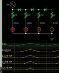
 

Here is an easy bargraph which responds to 0-5 V. It's made from 4 led's and 4 resistors and 3 diodes.

LED bargraph 0-5 V one diode between levels.png

The screenshot is how they appear when supply V=4v.

By using a diode between levels it automatically creates 0.6 V increments. Thus led's turn on more abruptly, whereas if you put resistors between each level the led's turn on gradually.

Maximum draw with all led's lit is about 48 mA. You can change resistor values to create desired brightness.

Or put 2 diodes between each level. But then you can only have 3 led'ls in the bargraph.
 

Status
Not open for further replies.

Similar threads

Part and Inventory Search

Welcome to EDABoard.com

Sponsor

Back
Top