Continue to Site

Welcome to EDAboard.com

Welcome to our site! EDAboard.com is an international Electronics Discussion Forum focused on EDA software, circuits, schematics, books, theory, papers, asic, pld, 8051, DSP, Network, RF, Analog Design, PCB, Service Manuals... and a whole lot more! To participate you need to register. Registration is free. Click here to register now.

Smps transformer windings

Status
Not open for further replies.

bmandl

Full Member level 4
Joined
Feb 26, 2010
Messages
207
Helped
3
Reputation
6
Reaction score
3
Trophy points
1,298
Location
Slovenia
Activity points
2,965
Hello guys,
I am looking at schematic of a SMPS for some audio system and I can't figure out, how the heck does that high frequency transformer work... I don't understand the winding for supplying IC3 (PWM controller). Is this primary or secondary winding and how can voltage be induced on it? I understand, that D20 is rectifire diode, so this is half-bridge rectifire for IC3 supply, but where does that voltage come from? I can measure variating DC voltage on cathode of that diode.
Thank you for answers.
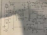
apr 16 ques about secondary copy.jpg

[found at: share.icloud. com /photos /0qscQj-OiHmP9LjktyoVIb1aw]
 
Last edited by a moderator:

It's a "secondary" sharing the same GND. Its purpose is to provide supply for the controller IC.

D20 is a diode with very short reverse recovery time. Usually a fast recovery, ultrafast recovery or schottky diode is used. Remember that the SMPS switches at high frequency so you need switching diodes. When we say that the diodes are rectifier diodes in smps, it's not like the silicon rectifier diodes in Bridge rectifiers.
 
Last edited:

It's a "secondary" sharing the same GND...
Maybe I should say it differently. It's a separate winding from the primary, usually called 'auxiliary winding' and shares the primary GND.

If you're thinking about startup, look at the connection to the HV pin of the controller IC.
 
Last edited:

So at first, IC3 is powered from high voltage of rectifier bridge for start-up, then it starts to oscillate and voltage is induced in auxiliary winding. Then it's supplied from there. Is it possible, that IC3 is somehow starting and stopping, because I can measure some variating DC voltage on diode D20, but SMPS is not working. I don't measure anything on any of secondary windings. I suppose that power transistor is not faulty, since I get voltage on auxiliary winding.
 

Try checking the waveform at the gate pin of IC3.

What equipment are you using for the measurement?

I can't find a datasheet to the IC. If you have a link to it, do post it here.


You need some form of protection to do measurements with oscilloscope on the primary side when the converter is powered by the mains. I use a differential 'voltage' probe.

I recommend that you work with DC power maybe from a bench top PSU at first.

We are going to work with the datasheet that you provided. So we will do a little bit of testing to ensure your power stage including your transformer is okay and properly connected.

First of all, ENSURE THAT THE OUTPUT TO YOUR SIGNAL GENERATOR DOES NOT HAVE A GROUND CONNECTION.

Now, break the feedback loop connection to the feedback pin so we can force it to be at 3V (VFB-N). Use a signal generator and impose a 3V DC (straight DC) signal on the feedback pin and then check to see whether you'd have an output.
 
Last edited:

remember to add a dummy load if you start powering it "open loop".
 

Use a simple isolation transformer for peace of mind. make sure the output of the isolation transformer is not connected to ground (you may kill the scope if you are not careful).
 

Also realize that the maximum duty cycle of the controller IC is considerably higher than your design duty cycle. So do you have to connect the signal generator to the IC before you turn on the converter input power.
 

Hm, I replaced IC3 and Q16 and I still don't get any output on gate pin of IC3. I get some sort of square waveform on VDD pin (5V 200ms inpuls every second). I tryed to put 3V to FB pin and still no output on gate pin. Do you think that new replaced IC3 died? What could be the cause of it? I do get some strange oscilation on HV pin every second (VPP around 130V).
 

I replaced IC3 and Q16 and I still don't get any output on gate pin of IC3.

I doubt they are the culprits.

First thing first: when you apply the power, the IC gets some power in the beginning from the secondary (auxiliary windings) coils. If that does not happen, the IC cannot start and the circuit cannot work.

The IC3 has no other way to get power and that should be the starting point - why it is failing to start!!

If the IC does not start osc, then the power to the IC will be cut off anyway. hence the circuit cannot be tested with power on because the IC will not have power.

Where do we start?

See if the Vdd pin of the IC is getting power for a few ms when power is first applied. This is easier said than done but you can test that with a LED in series with a 1K resistor connected to power pin of the IC and ground. The LED should flash very briefly.
 

I am constantly getting voltage on VDD pin (17V - 10V peak to peak) in 1s intervals.
 

What are the model number of your transformer and diodes?
 

Which diodes exactly? I have a service manual, but I don't know if I can post it here. I can tell you the name of the model and you can google service manual. It's quite accessible: PHILIPS MCM3150.
Thank you.
 

I am constantly getting voltage on VDD pin (17V - 10V peak to peak) in 1s intervals.

I am not clear about what you mean; do you mean you are getting pulses every second (approximately) on Vdd pin (about 10-17V)?

I believe that if the circuit does not start up during power on sequence, it will never start.

I request you to describe the information in more detail.
 

Not pulses. It oscilates like some kind of sinuse (it's not sinuse) with frequency of 1Hz. But I am doing measurements with AC disconnected, because my oscilloscope is grounded. I don't know if it's legit, but electrolytic capacitors still hold charge for very long time.
 

But I am doing measurements with AC disconnected, because my oscilloscope is grounded....

Good.

Please check the diodes, the filter caps and the zener connected to the Vdd of the regulator IC. What is the number of the regulator IC? I cannot read the diagram.

Check the filter capacitor first. No need to desolder, just make sure it is not shorted. Then check the diode connected to the aux winding (that supplies power to the regulator IC).

Also check the voltage at the IC pin that senses the high voltage. Make sure that pin is not shorted to any other pin nearby.

If the voltage at Vdd is like a sine curve, then the diode is probably gone. The diode should be a fast diode (but check the number if you can).

Please report what you find finally.
 

Status
Not open for further replies.

Similar threads

Part and Inventory Search

Welcome to EDABoard.com

Sponsor

Back
Top