Continue to Site

Welcome to EDAboard.com

Welcome to our site! EDAboard.com is an international Electronics Discussion Forum focused on EDA software, circuits, schematics, books, theory, papers, asic, pld, 8051, DSP, Network, RF, Analog Design, PCB, Service Manuals... and a whole lot more! To participate you need to register. Registration is free. Click here to register now.

EMI filter design for very low power switching power supply?

Status
Not open for further replies.

berger.h

Member level 5
Joined
Sep 30, 2016
Messages
93
Helped
0
Reputation
0
Reaction score
0
Trophy points
1,286
Activity points
2,355
Hello,
I have switching power supply for very low output power on 230V is input current 1-2mA and switching frequency 66kHz.
In design is on input EMI filer R1+R2+C1, and this ensure compliance with the EN55022 Class B emission limit.

I need to redesign it , and new design must have R2=0, I increase C1 from 2,2uF to 6,8uF and between RF1 and R1 add 10nF ceramics SMD C2 10nF.

Is it a good idea to reduce the missing R2?
Or how to better adjust the EMI filter?
Requirement, very small size (not big L on input) and low impedance on N.
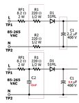
EMI.jpg
 

Well I guess you are using one of those lnkswitch type things.
The thing is they have an internal fet in the controller, and we have no way of damping the gate voltage turn on…because its all tucked away in the ic.
So we can filter all we like, but we cant make that fet switching any less noisy. You will know that that kind of fet switching creates high dv/dt in the circuit nodes…and yes, this leads to our best loved friend….common mode noise.
And its common mode noise which will force you to re-instate that resistor that you removed from the neutral line….because you need impedance in the loop of current that involves neutral and earth ( I know your circuit doesnt have an earth connection, but every object in the surroundings is connected to earth, so your circuit, like any other circuit, is stray capacitive coupled to earth….at multiple places.
So bring back your neutral resistor so that you have some common mode impedance.
To further reduce common mode noise, you need to make the switching node small, and preferably try and shield it from the surroundings…eg, somehow cover it with “quiet node” copper…eg copper connected to your circuit ground.
 

In general your still trying to do the same thing standard magnetic filters do but because your power is low you're choosing resistive impedance rather than inductive.

So study standard EMI filter designs and you'll see the common mode filtering treez is referring to which suggests R2 should be populated.
 
  • Like
Reactions: treez

    T

    Points: 2
    Helpful Answer Positive Rating
Yes you guessed it exactly.
I use Linkswitch-tn2 any as **broken link removed**
but I powered device where have GND on L potential and R2 in power supply would be inoperative.
 

Why is the DC ground be shorted to N (or L)? But if it is, there's no chance to have a common mode EMI filter which is probably the most important function.
 

Status
Not open for further replies.

Similar threads

Part and Inventory Search

Welcome to EDABoard.com

Sponsor

Back
Top