Continue to Site

Welcome to EDAboard.com

Welcome to our site! EDAboard.com is an international Electronics Discussion Forum focused on EDA software, circuits, schematics, books, theory, papers, asic, pld, 8051, DSP, Network, RF, Analog Design, PCB, Service Manuals... and a whole lot more! To participate you need to register. Registration is free. Click here to register now.

Shifting the waveform using op amp

Status
Not open for further replies.

Nihaludeen

Member level 2
Joined
Oct 29, 2017
Messages
46
Helped
0
Reputation
0
Reaction score
0
Trophy points
6
Activity points
460
I am trying to generate the SPWM using analog circuit, by comparing sine with triangular wave the output will be Sinusoidal PWM.

- Here i am generating Sine wave of 50 HZ using wein bridge oscillator. And it outputs good.
- Triangular wave is generated by square wave generator and integrator.
- Two waves are compared using comparator( LM393 )
Waveform generation circuits https://drive.google.com/open?id=1BFyOmhTnKfh69sRM6mcRJSJp97E919Gc


The two waves should be like the below images
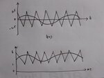
sine & triangle 2.jpg
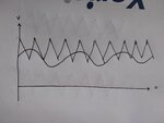
But i get like this
sine & triangular wave.jpg

How to shift the wave up or down according to the required amplitude ??
sine wave shifting waveform.jpg
 

attach your opamp circuit for sinewave , triangle and comparator with supply voltages shown.
 

Hi,

maybe you want something "self-aligning":

Use a DC-Blocking series capacitor on both signals and do DC biasing both signals to the same (average) level.
R to the bias voltage.

Klaus
 

The waveform get shifted good by using level shifter circuit. Thank you friends for your response..

- - - Updated - - -


Sure i will try it

- - - Updated - - -

Hi,

maybe you want something "self-aligning":

Use a DC-Blocking series capacitor on both signals and do DC biasing both signals to the same (average) level.
R to the bias voltage.

Klaus

I tried with decoupling capacitor at the output of the waveform . Which work good for a single circuit , for example Wien bridge oscillator added with decoupling capacitor at the end , gives ac sine wave of middle value zero volt. But when I add this circuit to an comparator the sine wave get shifted.
 

The two 10k resistors in series that divide the 9V into +4.5V and -4.5V are overloaded by the input bias current of the opamps. Use opamps with Jfet inputs that have an extremely low input bias current.
Why do your opamps have no part numbers?

- - - Updated - - -

If you add a coupling capacitor (a decoupling capacitor at the end) to the output of the Wien bridge oscillator then the comparator input has no DC reference voltage that should be at hlf the supply voltage. Then the DC bias current of the LM393 comparator causes its DC input to go positive.
 

Status
Not open for further replies.

Similar threads

Part and Inventory Search

Welcome to EDABoard.com

Sponsor

Back
Top