Continue to Site

Welcome to EDAboard.com

Welcome to our site! EDAboard.com is an international Electronics Discussion Forum focused on EDA software, circuits, schematics, books, theory, papers, asic, pld, 8051, DSP, Network, RF, Analog Design, PCB, Service Manuals... and a whole lot more! To participate you need to register. Registration is free. Click here to register now.

4 bit lcd display(PC066PGL) not working with PIC16F877A micro controller

Status
Not open for further replies.

mayasunny

Member level 3
Joined
Mar 21, 2019
Messages
56
Helped
0
Reputation
0
Reaction score
0
Trophy points
6
Activity points
481
Hi members,
i'm trying to interface 4 bit LCD with pic16f877a micro controller,
Code:
#pragma config FOSC = HS        // Oscillator Selection bits (XT oscillator)
#pragma config WDTE = OFF       // Watchdog Timer Enable bit (WDT disabled)
#pragma config PWRTE = ON       // Power-up Timer Enable bit (PWRT enabled)
#pragma config BOREN = ON       // Brown-out Reset Enable bit (BOR enabled)
#pragma config LVP = OFF        // Low-Voltage (Single-Supply) In-Circuit Serial Programming Enable bit (RB3 is digital I/O, HV on MCLR must be used for programming)
#pragma config CPD = OFF        // Data EEPROM Memory Code Protection bit (Data EEPROM code protection off)
#pragma config WRT = OFF        // Flash Program Memory Write Enable bits (Write protection off; all program memory may be written to by EECON control)
#pragma config CP = OFF         // Flash Program Memory Code Protection bit (Code protection off)

#include<xc.h>
#include"lcd.h"
#define _XTAL_FREQ 20000000

int main()
{
    TRISB = 0X00;                               // Configure all the LCD pins as output
    PORTB = 0X00;
    
    char i,a[]={"Good morning!"};

    lcd_init();
     
    lcd_write('H');
    lcd_write('e');
    lcd_write('l');
    lcd_write('l');
    lcd_write('o');
    lcd_write(' ');
    lcd_write('w');
    lcd_write('o');
    lcd_write('r');
    lcd_write('l');
    lcd_write('d');

    lcd_goto(0xc0);                            //Go to Next line and display Good Morning
    lcd_data(a);
    while(1);
}
and my lcd c file and h.file are below
Code:
#include<xc.h>
#include"lcd.h"
#define _XTAL_FREQ 20000000


//*********************************************************// 
#define LCD_RS PORTBbits.RB5	// Register select
#define LCD_EN PORTBbits.RB4	// Enable


//*********************************************************//
// write a byte to the LCD in 4 bit mode 
//*********************************************************//
void lcd_write(unsigned char c)
{
	PORTB = (PORTB & 0xF0) |  (c >> 4);                // Send higher nibble
	LCD_EN = 1;
    LCD_EN = 0;
	PORTB = (PORTB & 0xF0) |  (c & 0x0F);              // Send lower nibble
	LCD_EN = 1;
    LCD_EN = 0;
	__delay_ms(40);
}
//*********************************************************//
// 	Clear and home the LCD
//*********************************************************//
void lcd_clear(void)
{
	LCD_RS = 0;
	lcd_write(0x1);
	__delay_ms(2);
}
//*********************************************************//
// write a string of chars to the LCD 
//*********************************************************//
void lcd_data(const char *s)
{
	LCD_RS = 1;	// write characters
	while(*s)
		lcd_write(*s++);
}


//*********************************************************//
// Go to the specified position
//*********************************************************//
void lcd_goto(unsigned char pos)
{
	LCD_RS = 0;
	lcd_write(0x80+pos);
}
//*********************************************************//	
// initialise the LCD - Put into 4 bit mode 
//*********************************************************//
void lcd_init(void)         
{
	LCD_RS = 0;                     // write control bytes
	__delay_ms(15);                 // power on delay
	PORTB = 0x3;                    // attention!
	LCD_EN = 1;
    LCD_EN = 0;
	__delay_ms(5);
	LCD_EN = 1;
    LCD_EN = 0;
	__delay_ms(100);
	LCD_EN = 1;
    LCD_EN = 0;
	__delay_ms(5);
	PORTB = 0x2;                    // to set 4 bit mode
	LCD_EN = 1;
    LCD_EN = 0;
	__delay_ms(40);
	lcd_write(0x28);                // 4 bit mode, 1/16 duty, 5x8 font
	lcd_write(0x08);                // display off
//	lcd_write(0x0F);                // display on, blink curson on
	lcd_write(0x0C);                // display on, cursor off, blink off
	lcd_write(0x06);                // entry mode
  //  lcd_write(0x80);              // Move the cursor to beginning of first line
    
}

Code:
/* write a byte to the LCD in 4 bit mode */

extern void lcd_write(unsigned char);

/* Clear and home the LCD */

extern void lcd_clear(void);

/* write a string of characters to the LCD */

extern void lcd_data(const char *s);

/* Go to the specified position */

extern void lcd_goto(unsigned char pos);
	
/* intialize the LCD - call before anything else */

extern void lcd_init(void);

extern void lcd_putch(char);

/*	Set the cursor position */

#define	lcd_cursor(x)	lcd_write(((x)&0x7F)|0x80)

lcd is not displaying anything, im unable to find the out the problem. i need some hepl
 

Is it plugged in? Is it wired correctly? Have you tried using the built-in debugger?
 

Hi,

I recommend to read and post (a link to) the display datasheet.

Then use a voltmeter to check the supply and contrast voltages.
If they are OK then use a scope and check the digital control signals
..then the digital data signals.

...signal levels as well as timing

Klaus
 

    V

    Points: 2
    Helpful Answer Positive Rating
Be careful how you write to the PORT on these chips that do NOT have LAT registers - looking at some of the sequences you have, you are opening yourself up to the RMW problem. IF that is the case then the LCD controller will not be getting the signals that you think it is.
For example, you load the bottom nibble of PORTB and toggle RB4 in consecutive instructions - if there is any loading on on any of the pins then the RMW operation on the port can change the bit values.
You are better off to create a shadow register that you update and then write that to PORTB as a whole value.
A quick look on the Internet shows that the LCD controller is supposed to be a 'standard' Hitachi (I'm guessing HD44780 but only in 4-bit more). If that is the case then the timing of the initialisaiton sequence is critical. However looking at your code, you would seem to be OK (except for an excessively long delay in 'lcd_write()').
If the device has a 'contrast' pin, then turn up the voltage on that until you get all of the character locations showing as faint blocks of dots and then back it off a little. If the contract is down too low then it is possible the characters are there but just not showing - setting the contract level as I've mentioned should make then visible.
Susan
 

Are you sure the timing of the I/Os is correctly sized? According to the snippet below taken from your code, and based on the crystal frequency, pin E is kept in high level by only 200 ns:

Code:
LCD_EN = 1;
LCD_EN = 0;

Check the LCD controller datasheet about timming specifications.
 

yes barry, it is wired correctly, my lcd is (PC066PGL), for this display pin out i have is 1-4,7-10,19-22 are ground, 11-14 data lines, pin 5-EN, pin 6 -RS, pin 18 - Vdd and pin 17 - Vled+
are my EN,Rs connections right?

- - - Updated - - -

Are you sure the timing of the I/Os is correctly sized? According to the snippet below taken from your code, and based on the crystal frequency, pin E is kept in high level by only 200 ns:

Code:
LCD_EN = 1;
LCD_EN = 0;

Check the LCD controller datasheet about timming specifications.

i read some where that the delay should be in 'us', i tried with delay in 'us' , please tell me how can you say that delay in ns based on crystal frequency

- - - Updated - - -

Be careful how you write to the PORT on these chips that do NOT have LAT registers - looking at some of the sequences you have, you are opening yourself up to the RMW problem. IF that is the case then the LCD controller will not be getting the signals that you think it is.
For example, you load the bottom nibble of PORTB and toggle RB4 in consecutive instructions - if there is any loading on on any of the pins then the RMW operation on the port can change the bit values.
You are better off to create a shadow register that you update and then write that to PORTB as a whole value.
A quick look on the Internet shows that the LCD controller is supposed to be a 'standard' Hitachi (I'm guessing HD44780 but only in 4-bit more). If that is the case then the timing of the initialisaiton sequence is critical. However looking at your code, you would seem to be OK (except for an excessively long delay in 'lcd_write()').
can you explain it little more

If the device has a 'contrast' pin, then turn up the voltage on that until you get all of the character locations showing as faint blocks of dots and then back it off a little. If the contract is down too low then it is possible the characters are there but just not showing - setting the contract level as I've mentioned should make then visible.
Susan
my contrast pin is connected to potentio meter, i set it to max level
 

i read some where that the delay should be in 'us', i tried with delay in 'us' , please tell me how can you say that delay in ns based on crystal frequency

Cryrstal Frequency (Fc): 20000000 Hz
Instruction Time (T): 4 x 1/Fc

So, T = 1/5000000 Hz = 0,2 us
 
If the contrast voltage is set to maximum, does that mean high contrast (in which case all you will see are all of the dots lit up in the character squares) or low contract (in which case you will see nothing).
You need to adjust the contrast as I described to make sure that you will be able to see the characters when they are displayed.
Looking at an HD44780 data sheet, the *minimum* pulse width of the 'E' pin should be 230nS with a 5V Vcc but that extends to 450nS for lower supply voltages. Personally I would be looking for 500nS minimum to be safe. You can achieve that by putting at least 3 (preferably 4 to be safe) NOPs between raising and lowering the pin.
Susan
 
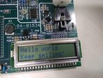
my display now working properly, but the problem is it displaying some garbage characters when run the code first time, from second time it displaying properly,
 

Hi,

I assume there is a timing problem..

--> I see no other chance than to take the datasheet and compare each specification item by itmem with your application.
(Code, scope pictures).

It begins with applying voltage --> check when the supply voltage is valid --> check time until you send the first instruction.
(Maybe there is a RESET signal involved.)
Then check if the first byte really has the value that you expect...


Klaus
 

Hi,

I assume there is a timing problem..

--> I see no other chance than to take the datasheet and compare each specification item by itmem with your application.
(Code, scope pictures).


Klaus

Thank you for response klausST, i don't have PC066PGL datasheet, but i do have HD44780, will it useful for that

;It begins with applying voltage --> check when the supply voltage is valid --> check time until you send the first instruction.
(Maybe there is a RESET signal involved.)
Then check if the first byte really has the value that you expect...

Klaus
can you explain it more
 

Hi,
i don't have PC066PGL datasheet, but i do have HD44780, will it useful for that
I can´t anwer this. I don´t have a PC066GL in my hands.
And I don´t know whther there is a HD44780 assembled and whether there is additional circuitry that "modifies" the specification.

--> Don´t buy parts they don´t come with a datasheet.
Otherwise it´s your own risk if it does not work like you expect.

can you explain it more
The given recommendation makes sense only with the specification of the datasheet.

Klaus
 

actually whatever the lcd display i have is 90's display,
 

Based on the display number, this is probably a display using a Samsung KS0066U instead of a HD44780 but they are almost identical. Get hold of the KS0066 data sheet to look for timing differences just in case.
actually whatever the lcd display i have is 90's display,
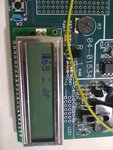
What do you mean by that? Show us a picture of the display and tell us what you think it should be showing.

Brian.
 

I think we all know what an LCD module looks like.
I meant a picture of the characters on the display when the program isn't working and what you expected it to show.

Please post images directly on Edaboard, if you use external links we have no guarantee where they go or if the image has been removed.

Brian.
 

lcd img.jpg this is a snap
 

Hi,

and what you expected it to show.
Where can we find "what you expected to be printed on the LCD"?

Klaus
 

The electronics around the contrast setting is obviously working properly so it comes down to a software error. It does seem to be at least partially initializing the LCD or it wouldn't display anything so I would guess you are looking at a timing issue.

I am hoping you have noted the previous comments about RMW and timing. Please post your present code so we can look again.

Brian.
 

Status
Not open for further replies.

Similar threads

Part and Inventory Search

Welcome to EDABoard.com

Sponsor

Back
Top