Carvalhoatx
Newbie level 3
Dear All!,
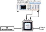
Could anyone help to assembly a setup test. I have an IQ Quadrature Modulator (Polyphase ) with: 4 input`s (I, Ī and Q, ΞQ). Further, my RF LO(Local osc.) and RF Output (Mod. Signal). I have also, an Arbitrary Waveform Generator, which I would like to use to create my "I and Q". A RF signal Generator to my LO too.
IF I want a signal em 2,5 GHz, which will be my setting? Could you help me? If anyone want details I will share it....as well as info about my equipment... Thank you
