jts1705
Newbie level 3
Hello everybody,
I am a student who is developing a pressure sensor device for a medical application. I need to measure pressures between 0 and 50mmHg. Therefore, I am using arterial pressure sensors that suit my purposes (https://www.icumed.com/products/critical-care/blood-pressure-monitoring/transpac-it.aspx).
I need to amplify, filter and condition the signal before Arduino UNO can read it.
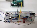
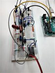
I've designed an schematic that I think can work, but now I am trying everything in a protoboard and it does not work. I have tested with a voltmeter partial voltages and the DCDC converter seems to be not working good. It does not give any output signal. I have checked again its datasheet and seems like it has a CTRL pin... but I do not really think it is the reason why it does not work. (https://eu.mouser.com/datasheet/2/468/RS-S_D_Z-958418.pdf). I do not know if the DCDC converter is broken or if I have performed a mistake before...
I would be very very very thankful if any of you could give me his/her opinion.
I attach the schematic and two photos of the protoboard.
Thank you very much!!


