Continue to Site
Follow along with the video below to see how to install our site as a web app on your home screen.
Note: This feature may not be available in some browsers.
Hi.
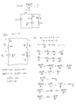
At t=0+ Vc=16V and I=2A then V_R12+V_R8 = (12+8)*2 = 40V ==> VL = Vc-(V_R12+V_R8) = 16 - 40 = -24V
Hi.
At t=0+ Vc=16V and I=2A then V_R12+V_R8 = (12+8)*2 = 40V ==> VL = Vc-(V_R12+V_R8) = 16 - 40 = -24V
Hi!
Is my method above incorrect can you pinpoint at which point I messed it up. Please bear with me.
Doesn't Vc change due to current flow? That's not considered in your calculation.
Doesn't Vc change due to current flow? That's not considered in your calculation.
Of course, but has no effect on the current derivative at t=0+
Just think on the standard RLC: Vc + Vr + VL = 0
But VL = L I' = L Vr'/R
then Vc + Vr + (L/R)Vr' = 0
At t=0+ only the instantaneous voltage,current and L/R define Vr'
...
Why is the actual direction of the current through the inductor and the actual polarity of the voltage across the inductor does not agree with the passive sign convention?
Hello!
Why is the actual direction of the current through the inductor and the actual polarity of the voltage across the inductor does not agree with the passive sign convention?