Continue to Site

Welcome to EDAboard.com

Welcome to our site! EDAboard.com is an international Electronics Discussion Forum focused on EDA software, circuits, schematics, books, theory, papers, asic, pld, 8051, DSP, Network, RF, Analog Design, PCB, Service Manuals... and a whole lot more! To participate you need to register. Registration is free. Click here to register now.

Keysight ADS significant discrepancy between circuit simulation and Momentum 11 GHz!

Status
Not open for further replies.

usx

Member level 2
Joined
Jan 28, 2016
Messages
43
Helped
3
Reputation
6
Reaction score
3
Trophy points
8
Activity points
392
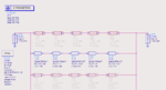
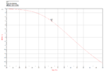
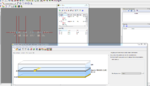
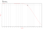
I'm designing a basic stepped impedance LPF, with -3dB at 34GHz. I simulated it with transmission lines first, then with microstrip lines. I get -3dB at 34GHz, as expected. Next, I import it into Momentum, use appropriate ports but my -3dB corner now shows at 22.8, that is, I am off from circuit simulation by 11 GHz. I checked my setup, I used appropriate ports (TML), high mesh density of 50 and my substrate setup also seems to be the same for both simulations. What is wrong with my setup?

edit: I changed corner frequency in circuit simulation from 34GHz to 46GHz and Momentum's corner changed to 25.3GHz, and when I changed it from 46GHz to 24GHz, Momentum simulation went down to 18.3GHz.
 

Attachments

  • 1.PNG
    1.PNG
    44 KB · Views: 238
  • 2.PNG
    2.PNG
    36.2 KB · Views: 227
  • 3.PNG
    3.PNG
    120.6 KB · Views: 253
  • 4.PNG
    4.PNG
    32.1 KB · Views: 196
Last edited:

MSTLINE Models are valid for certain W/L otherwise the model discrepancy increases.Have you ever seen a Warning Message while the Circuit is simulated ??
 

First, you need to use the microstrip schematic models properly, including MSTEP, MCROS and MLOC. It is not accurate to just cascade MLIN with very different width. There are examples included with ADS.

One example how to build this structure from schematic models:
https://muehlhaus.com/support/ads-application-notes/em-parameters-momentum

Next, your EM port calibration is off because you attached the EM pin to the wide stub. Add a short piece of 50 Ohm line at BPF input and output. Only then, ADS Momentum will use the proper port excitation (width) for 50 Ohm feed.
 
Last edited:

First, you need to use the microstrip schematic models properly, including MSTEP, MCROS and MLOC. It is not accurate to just cascade MLIN with very different width. There are examples included with ADS.

One example how to build this structure from schematic models:
https://muehlhaus.com/support/ads-application-notes/em-parameters-momentum

Next, your EM port calibration is off because you attached the EM pin to the wide stub. Add a short piece of 50 Ohm line at BPF input and output. Only then, ADS Momentum will use the proper port excitation (width) for 50 Ohm feed.

Thanks, I've corrected my setup. Now, circuit setup is off from Momentum by 3-5 GHz. Now I'm struggling to tune the values for ADS layout; when I change values of high impedance elements, frequency response shifts right but it also introduces a 1-2 dB ripple in passband.
 

Thanks, I've corrected my setup. Now, circuit setup is off from Momentum by 3-5 GHz.

Schematics model are not exact, but that's a lot. Maybe your Momentum setup is still bad.

Did you implement the little extra 50 ohm feedline, to make sure your port width at the feed is correct?
Also, did you include metal thickness is Momentum (thick metal model instead of infinitely thin?
And finally, high mesh density is the key to accurate EM simulations, so make sure to enable edge mesh.

If you are able to reach reasonable agreement between schematic model and EM, you can optimize fast at schematic level. Otherwise, you will need to use EM-based optimization. My appnote might give some hints how to create a parametrized subcircuit for the emModel workflow.

Yes, I set metal to 17 microns. I added a 50Ω feed line. I set both ports to TML using edge pin. I also kept seeing that my Momentum is consistently off by 5-5.6 GHz from ADS circuit so I adjusted and tuned my circuit accordingly.

I did however ran into issue of running this structure at higher frequencies to see harmonic and fly as I was getting errors that distance between pins is electrically large. I contacted Keysight and they said that MOM simulation becomes inaccurate at higher frequency but I digress.

Thanks for your help.
 

Yes, I set metal to 17 microns.

Be careful ... When using "sheet" model, metal thickness is only used for loss calculation (but not field simulation). To make sure actual thickness (including metal side wall effects) is properly modelled for the fields, you need to set the metal model to "intrude into substrate" or "expand the substrate". Otherwise, you simulate a flat sheet only.

I also kept seeing that my Momentum is consistently off by 5-5.6 GHz from ADS circuit so I adjusted and tuned my circuit accordingly.

That's a dangerous method, be very careful to double check things.

I did however ran into issue of running this structure at higher frequencies to see harmonic and fly as I was getting errors that distance between pins is electrically large. I contacted Keysight and they said that MOM simulation becomes inaccurate at higher frequency but I digress.

It's difficult to advise without seeing your models. From my 20 years experience as an EM expert: MoM is accurate at higher frequencies when the setup, including ports, is done properly. What you showed above looks rather trivial to me, and should show excellent accuracy. Claims that you need to switch to FEM are often sales pitch, with little technical reasoning.

It indeed becomes a bit tricky at frequencies where the substrate is too thick and the line is overmoded - then port calibration will fail, but that's also true for your VNA's TRL calibration when you try to measure the filter in real life. That's an issue with overmoded lines on thick substrates, not limited/related to the EM solver.
 
Last edited:

Status
Not open for further replies.

Part and Inventory Search

Welcome to EDABoard.com

Sponsor

Back
Top