Continue to Site

Welcome to EDAboard.com

Welcome to our site! EDAboard.com is an international Electronics Discussion Forum focused on EDA software, circuits, schematics, books, theory, papers, asic, pld, 8051, DSP, Network, RF, Analog Design, PCB, Service Manuals... and a whole lot more! To participate you need to register. Registration is free. Click here to register now.

Independent PWMs using MPLABX easy configurator

Status
Not open for further replies.

jlopez2022

Newbie
Joined
Apr 1, 2019
Messages
4
Helped
0
Reputation
0
Reaction score
1
Trophy points
1
Activity points
30
I used the easy configurator to configure dspic33EP128GM604
I programmed to run FCY=50MHz and checked using the scope.

Then I made following setup using PWM easy mode:

MCHIP-1.jpg

I programmed: 50MHz/16/0x271=5khz that is the stablished PWM base clock

Then in the PWM number 6 I made:
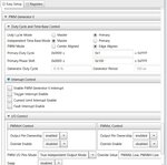
MCHIP-2.jpg

My idea is to write the PWM dty cycle making:

Code:
PDC6=(uint16_t) (percentage6H*0x271);//6H
SDC6=(uint16_t) (percentage6L*0x271);//6L

Where percentage6H and L is a float number between 0 and 1

Unfortunately it does not work. There are a lot of examples of code but writting directly the registers
 

Hi,

Unfortunately it does not work.

This is no error description.

Give:
* test conditions
* your expectations
* what you see instead

Klaus
 

There are no errors or notifications, only no pwm output.

In a deshesperte action I tried this function with same result:
Code:
void test2()
{
	PTCONbits.PTEN       = 0;
	
	TRISCbits.TRISC6 = 0;                  /* Set as a digital output */
	TRISCbits.TRISC7 = 0;                  /* Set as a digital output */
    PTCON2 = 0x04;
	PTPER = 0x271; 
	/*~~~~~~~~~~ PWM6 Configuration ~~~~~~~~~~~~~~~~~~~~~~~~~~~~*/    
	IOCON6bits.PENL      = 1;   /* PWM1L is controlled by PWM module */ 
	IOCON6bits.PENH      = 1;   /* PWM1H is controlled by PWM module */
	IOCON6bits.PMOD      = 0;   /* Select Independent Output PWM mode */
    PWMCON6 = 0x80;//-->this was set and removed without results
	PDC6 = 100;                 /* Initial Duty cycle */ 
    SDC6=  200;                 /* Initial Duty cycle */
	DTR6    = 0;                /* Deadtime setting */
	ALTDTR6 = 0;                /* Deadtime setting */
	PHASE6 = 0;                 /* No phase shift */
	SPHASE6 = 0;                /* No phase shift */

	PTCONbits.PTEN       = 1; /* Enable the PWM Module */    
}
 

Hi,

There are no errors or notifications, only no pwm output.
This is at least a bit of information.
But: Is it HIGH, LOW, or high impedance?

Does the microcontroller work at all... is there power supply?
What did you do to debug the problem? (toggling any IO, for example) What are the results?

Please suppport us - otherwise we can´t help you.

Klaus
 

Finally I found the error is avoided by write this code inside pwm.c file at PWM_Initialize() function just before PTCON = 0x8000; (or PTCON = 1; ):

Code:
FCLCON1 = FCLCON2 = FCLCON3 = FCLCON4 = FCLCON5 = FCLCON6 = 0x0003;


Thats enables external period reset mode.

I should recommend to microchip to add that line in the easy configurator.
Also include the SDC1-6 duty cycle setup :)
 

Status
Not open for further replies.

Similar threads

Part and Inventory Search

Welcome to EDABoard.com

Sponsor

Back
Top