Genovator
Advanced Member level 2
Hello Members
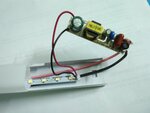
I have a LED Batten tube (~ 4ft) which stopped working recently. I opened it up and found it is using a buck converter with a switching controller IC (NON ISOLATED). Nothing was burnt or non functional so the switching controller must be the culprit. Also I can't read its part number, nor I can order a new one. The LED strip has a total of 87 surface mount LEDs with 29 in series and 3 such in parallel (3P-29S configuration). Rated power of the batten is 20W with Power Factor of 0.9. So I am assuming each LEDs are going to consume around 200mW (20W x 0.9 = 18W / 87 = ~200mW). I don't know the LED's part number, but I have to assume their breakdown voltage will lie in between 3.3v to 3.6v. Given 29 in series I have to supply around 100v.

I was planning to build my own LED driver. I designed a circuit using a flyback transformer (coiled by myself; 150:50 just to experiment with) but hit with the common problem a flyback trafo has: transient voltage spikes. I tested with just 12v and my multimeter gave reading of over 1000v :bsdetector: on both primary and secondary sides. I am worried what would happen if I try with a rectified 220v. I don't have enough room to implement more components and suppress the spikes. So I am looking for a solution with lower part count.
So I want to stick with the same method they were using in their product: a buck converter. Also I don't have enough room for isolation. So a simple non isolated circuit would be my best choice.
So before I proceed, I wanted to know if it is suitable to step down from 310v to 100v using a non isolated buck circuit, or are their any caveats. Also, what are the things which I need to consider and keep in mind?
P.S.: I know high voltage DC can kill me. I can take care of that! :fight:
I have a LED Batten tube (~ 4ft) which stopped working recently. I opened it up and found it is using a buck converter with a switching controller IC (NON ISOLATED). Nothing was burnt or non functional so the switching controller must be the culprit. Also I can't read its part number, nor I can order a new one. The LED strip has a total of 87 surface mount LEDs with 29 in series and 3 such in parallel (3P-29S configuration). Rated power of the batten is 20W with Power Factor of 0.9. So I am assuming each LEDs are going to consume around 200mW (20W x 0.9 = 18W / 87 = ~200mW). I don't know the LED's part number, but I have to assume their breakdown voltage will lie in between 3.3v to 3.6v. Given 29 in series I have to supply around 100v.

I was planning to build my own LED driver. I designed a circuit using a flyback transformer (coiled by myself; 150:50 just to experiment with) but hit with the common problem a flyback trafo has: transient voltage spikes. I tested with just 12v and my multimeter gave reading of over 1000v :bsdetector: on both primary and secondary sides. I am worried what would happen if I try with a rectified 220v. I don't have enough room to implement more components and suppress the spikes. So I am looking for a solution with lower part count.
So I want to stick with the same method they were using in their product: a buck converter. Also I don't have enough room for isolation. So a simple non isolated circuit would be my best choice.
So before I proceed, I wanted to know if it is suitable to step down from 310v to 100v using a non isolated buck circuit, or are their any caveats. Also, what are the things which I need to consider and keep in mind?
P.S.: I know high voltage DC can kill me. I can take care of that! :fight:

