Continue to Site

Welcome to EDAboard.com

Welcome to our site! EDAboard.com is an international Electronics Discussion Forum focused on EDA software, circuits, schematics, books, theory, papers, asic, pld, 8051, DSP, Network, RF, Analog Design, PCB, Service Manuals... and a whole lot more! To participate you need to register. Registration is free. Click here to register now.

push pull design problem

Status
Not open for further replies.

miladrk

Newbie
Joined
Aug 14, 2018
Messages
2
Helped
0
Reputation
0
Reaction score
0
Trophy points
1
Activity points
21
I made a push-pull converter using sg3525a.

my problem is the output voltage will drop when I connecting 100-watt load or more.

input voltage is 24 volt and the output is 350 volt. the frequency is 100khz. using MOSFET irfp4568. using RC snubber with c=6 nF and R=2.5ohm. and driving the MOSFET with hcpl3120 positive and negative gate voltage. I am using ferrite core EE 55/28/21 to get 1kw output power.
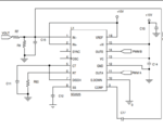
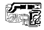
and these are the schematic and PCB Capture1.PNGlead-acid-battery-charger.giflayout.
 

Hi,

you try to test us? ... Whether we recognize that you post a different circuit than you describe..

Klaus
 

I made a mistake. I uploaded a wrong image.
this is the control schematic.
Capture.PNG
 

Hi,

don´t be surprised if nobody spends a lot of time to find out your complete schematic and how the parts are arranged on your PCB...

Klaus
 

output is 1000 W at 350 V, so about 3 A.
input is 24 V 1100 W, for 46 A. note: I added 10% for losses and overhead.

if the output drops at 100W (about 0.3 A), the input is at about 5 A or about 125 W.

how much power can your 24 V source provide?
 

I'd look to how you're abusing that linear regulator,
thermal limit perhaps?
 

Status
Not open for further replies.

Similar threads

Part and Inventory Search

Welcome to EDABoard.com

Sponsor

Back
Top