Continue to Site

Welcome to EDAboard.com

Welcome to our site! EDAboard.com is an international Electronics Discussion Forum focused on EDA software, circuits, schematics, books, theory, papers, asic, pld, 8051, DSP, Network, RF, Analog Design, PCB, Service Manuals... and a whole lot more! To participate you need to register. Registration is free. Click here to register now.

Gilbert cell mixer implementation

Status
Not open for further replies.

promach

Advanced Member level 4
Joined
Feb 22, 2016
Messages
1,199
Helped
2
Reputation
4
Reaction score
5
Trophy points
1,318
Activity points
11,636
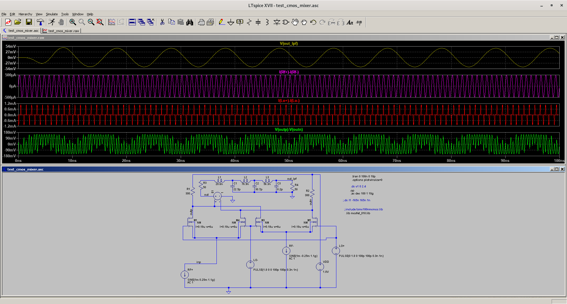
In this paper 15.1 mW 60 GHz up-conversion mixer with 4.5 dB gain and 57.5 dB LO-RF isolation , I have three questions :

1) Have anyone designed a balun in spice software ? Is it doable ?

2) How to implement TL1 and TL2 (inductor implemented using transmission line) in spice software ?

3) How to derive the conversion gain expressions ((1) and (2)) for the up-conversion mixer circuit with and without negative resistance compensation in the paper ?

uH4CgJn.png
 

1, https://leleivre.com/rf_LCBalun.html or use voltage controlled voltage sources with resistor termination if you want ideal balun, so yes, doable
2, there are spiral inductors with foundry models, usually these are used
3, I have no idea, and I have limited acces to IEEE, but on figure mixer the derive of conversion gain probably not so different from downconversion mixers, which is well described in Razavi RF microelectronics if I remember well.
 
SPICE Software is not enough to design a Balun or any kind of Planar Circuit @ 60GHz..
You'll need a EM Simulator to verify these structures.If you have a PDK for 60GHz, you'll also need either high performance Circuit Simulator such as Keysigh ADS or AWR MWOffice or Cadence ADE Spectre in collaboration with a EM Simulator yet like Sonnet or HFSS etc.
It's almost impossible to design such circuits with ordinary SPICE circuit simulator..
 

Oh, I didn't see it is 60GHz. I am not sure actually how transistor models are trustable there, I have never worked with similar, sorry.
 

I have finished the mixer simulation , but I am not sure how to interface the balun circuit for RF+ and RF- current signals.

Waveforms.png


HQVFcHy.png
 

1) How do I interface LC balun with mixer using differential current RF+ and RF- input signals ?

2) How should I deal with the load impedance (RL) for LO+ and LO- which is almost infinite because it is mosfet gate ?

Waveforms.png


vUe5zwV.png
 

The LO Biasing is not correct, you should apply a DC Operating Point to drive MOS Transistors.
First, you have to find Optimum Load Impedance for Mixer which will give you best Harmonic Suppression and Higher Output Voltage then you can connect the Balun to the Mixer differentially.Pay attention to DC Biasing..
 

The LO Biasing is not correct, you should apply a DC Operating Point to drive MOS Transistors.

Did you see pulse() stimulus ? I have already stated 1.8V , why is that problem for DC biasing ? Did I miss anything ?

you have to find Optimum Load Impedance for Mixer which will give you best Harmonic Suppression and Higher Output Voltage then you can connect the Balun to the Mixer differentially

and how to find this optimum load impedance ?
 

Did you see pulse() stimulus ? I have already stated 1.8V , why is that problem for DC biasing ? Did I miss anything ?
and how to find this optimum load impedance ?
1.8V is AC peak Voltage only but this source will drive the MOS Transistors beyond the Vth ( Treshold Voltage ) so Transistors will conduct like C-Class.. You should add a DC Biasing Voltage to drive them A-Class.. ( They somehow work but such kind driving is not correct )
In order to optimize the Load, you can make a Sweep Analysis at a fixed frequency.Change the Load Resistance and observe Mixer Gain, Harmonic Levels, Output Level.Then find an Optimum one.
 
1.8V is AC peak Voltage only but this source will drive the MOS Transistors beyond the Vth ( Treshold Voltage ) so Transistors will conduct like C-Class.. You should add a DC Biasing Voltage to drive them A-Class

Wait, how is adding a DC bias make them class-A amplifier ? I am not doing amplifier stuff.

In order to optimize the Load, you can make a Sweep Analysis at a fixed frequency.

Mixer is not linear if you study how it works. So, we cannot use .AC() analysis since AC is using linearized circuit model
 

Wait, how is adding a DC bias make them class-A amplifier ? I am not doing amplifier stuff.
Mixer is not linear if you study how it works. So, we cannot use .AC() analysis since AC is using linearized circuit model

I didn't say that you're doing A-Class Amplifier, I said the Commutation MOS Transistors are working C-Class so the Switching Current does not flow 360 degree..
The Commutation MOS should be driven A-Class because if the Current becomes C-Class the Harmonic Levels will be too high..
I don't mention AC Analysis, I know the Mixers are Nonlinear and you can do it ( Sweeping Load ) with HB too therefore I said SPICE Simulator is not good enough for RF Simulations, you have to use more professional simulators.
 
the Commutation MOS Transistors are working C-Class so the Switching Current does not flow 360 degree.. The Commutation MOS should be driven A-Class because if the Current becomes C-Class the Harmonic Levels will be too high..

Wait, why is my mixer circuit working C-class ?

and how is class-C related to harmonics levels ? Anyone care to explain ?

class-c-power-amplifier-circuit.png


I know the Mixers are Nonlinear and you can do it ( Sweeping Load ) with HB

As for HB , are you referring to Harmonic Balance Analysis ?
 
Last edited:

You don't need to refer to terms like class-A or class-C to describe the behaviour of your mixer. You decided to drive the mixer with 1.8V LO level which makes it operating as commutator switch rather than "linear" mixer. I presume, you did that for a specific reason.


With LTspice, transient analysis and FFT are the appropriate means to analyze your circuit. They aren't inaccurate, but the analysis is much more time consuming than with using advanced tools like harmonic balance.

If designed correctly, high level mixers are causing less harmonics and intermodulation products for the RF signal. They are used e.g. in spectrum analyzers and wide band receivers. LO frequency and RF preselection must be chosen respectively.

By the way, your way of including pictures in the posts prevents that they can be easily zoomed. Pictures with many details like the LTspice schematics and waveforms become effectively unreadable for me.
 

Look at you original picture why the author used a biasing circuit to drive both Commutation Part and Amplifier Part of the Gilbert Cell cell..
uH4CgJn.png
 
@BigBoss

See the following single-to-differential converter which does not uses DC biasing. Do you think this is alright ?

7RAhIck.png
 

@BigBoss
See the following single-to-differential converter which does not uses DC biasing. Do you think this is alright ?
Principal schematic could be shown only..They don't show generally biasing circuit and other details
Anyway, I have told you what I know about them, the rest is up to you..
 

Status
Not open for further replies.

Part and Inventory Search

Welcome to EDABoard.com

Sponsor

Back
Top