Continue to Site

Welcome to EDAboard.com

Welcome to our site! EDAboard.com is an international Electronics Discussion Forum focused on EDA software, circuits, schematics, books, theory, papers, asic, pld, 8051, DSP, Network, RF, Analog Design, PCB, Service Manuals... and a whole lot more! To participate you need to register. Registration is free. Click here to register now.

Current source output stage

Status
Not open for further replies.

AlexandreRibas

Newbie level 3
Joined
Oct 29, 2016
Messages
4
Helped
0
Reputation
0
Reaction score
0
Trophy points
1
Activity points
26
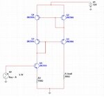
I'm trying to design a current source with some particularities. Based on the modified Wilson current source, I need an output stage that provides no voltage when there is no load, that's the problem, because when there is no load on the circuit, the output voltage is maximum (close to V1 voltage).
So, I need to do something that pulls the Q4 collector voltage to ground when no load and provides the current controlled by V2 and Q5 when some load is attached. Can someone help me with this?


circ.jpg
 

Hi,

Impossible.

for a constant current source: The higher the load resistance the higher the output voltage.
In reality output voltage will be limited by supply voltage... and circuit.

No load usually means infinite resistance --> maximum of voltage.

But you want the opposite.

***
Now let´s say you define a "upper resistance limit" ... at which the output should switch to GROUND.

Then you never have the chance to go back into current regulation again, because with NO ouput voltage you will never know if the load resistor is within the valid range....

****

What you describe is a solution.... or how you want the solution to be.

Better describe the application, to better understand the problem or the real requirement.

Klaus

Yes, the solution that I thought also prevents it from returning to the previous state, because when no voltage would be impossible to provide current again.

This is to be used on an electro stimulator and I want an output that would be grounded when no load for security.
 

Jack phone connectors have built-in switches for example to sense load connection, you could use that in a real case to set initial ground at the output.
In simulation not clear why would you need a solution like this, and it depends on simulator what kind of spice,verilog module is availabe to set strong pull-down for a specified node, when load is detached.
So, which "electro simulator" are you using?
 

As said you have a fundamental problem because if you don't provide voltage you won't ever see current and can't know when to exit this state.

So I'd choose a different criteria perhaps just a small voltage and when you sense a small current (voltage change) you fully enable your current source. 1V biased through a 1meg resistor qualifies as safe and secure in my mind and could easily do this job.


The only other alternative is trying to detect a 'pop' or some other small signal that results from an external connection and the [probably] inevitable capacitance and voltage mismatch the external device will have. Though this doesn't seem reliable to me.
 

So I'd choose a different criteria perhaps just a small voltage and when you sense a small current (voltage change) you fully enable your current source. 1V biased through a 1meg resistor qualifies as safe and secure in my mind and could easily do this job.

It makes sense, I'll think about this possibility. Thanks
 

Hi,

I recomend to post realistic situations.
* what is the usual working load resistance?
* at which level you call it "unconnected"
* what is the max. output voltage?
* what maximum output voltage do you allow in "shut OFF" mode?
... and so on.

Please understand: We don´t know whether your realistic load resistance is in the range of microOhms or GigaOhms. The same is with current and voltage...

Usually one could expect any timing requirements, too.

Klaus

- - - Updated - - -

Hi,

what now? "simulator" or "stimulator"?

Klaus
 

Status
Not open for further replies.

Similar threads

Part and Inventory Search

Welcome to EDABoard.com

Sponsor

Back
Top