Continue to Site

Welcome to EDAboard.com

Welcome to our site! EDAboard.com is an international Electronics Discussion Forum focused on EDA software, circuits, schematics, books, theory, papers, asic, pld, 8051, DSP, Network, RF, Analog Design, PCB, Service Manuals... and a whole lot more! To participate you need to register. Registration is free. Click here to register now.

Regulated Joule thief, how to increase current?

Status
Not open for further replies.

neazoi

Advanced Member level 6
Joined
Jan 5, 2008
Messages
4,122
Helped
13
Reputation
26
Reaction score
15
Trophy points
1,318
Location
Greece
Activity points
36,951
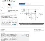
Hi I have found and tested this circuit https://simplifier.neocities.org/joule.html The author said that it starts to reduce voltage after 20mA of drawn current or so.
My MCU project requires 75mA and I have to allow for some margin say 100mA.
Note, I have tested the circuit with several common mode chokes (1:1:) and a custom wound 3t:3t toroid. The tests have been done with 2n2222 and bd139 transistors only, not the 2n3055 that the circuit shows. For the diode I used a 1n4003 but a schotky diode showed no difference.

Now, how can I increase the current capability of this circuit so that 5v could be achieved at near 100mA?
I mean what component parameters affect that?
 

For 100mA out you need a 1A transistor with high gain, e.g. BCX55 and a 1:5 transformer also the diode should be a schottky 1A 40V for better efficiency
 
  • Like
Reactions: neazoi

    neazoi

    Points: 2
    Helpful Answer Positive Rating
For 100mA out you need a 1A transistor with high gain, e.g. BCX55 and a 1:5 transformer also the diode should be a schottky 1A 40V for better efficiency

Thanks a lot!
The BD139 I have tried seems to be ok, it has an hfe of 100-250 just like the BCX55 and 1.5A Ic, better than the BCX55.
So I shall try 1:5 turns instead? I have tried 3t:18t at a small toroid (ft37-43) and it did not work out.
 

I'm going to amend my post - 1:2 transformer and a larger core - the issue with the so called joule thief circuit is that you can't store much energy in a toroid of high-u ferrite with no gap - and you can't have an air gap else the saturation turn off won't work so well - so you need to double up the core to double the energy transfer, or a bigger core, i.e. double the core area for double the power, triple for triple ...
 
  • Like
Reactions: neazoi

    neazoi

    Points: 2
    Helpful Answer Positive Rating
I'm going to amend my post - 1:2 transformer and a larger core - the issue with the so called joule thief circuit is that you can't store much energy in a toroid of high-u ferrite with no gap - and you can't have an air gap else the saturation turn off won't work so well - so you need to double up the core to double the energy transfer, or a bigger core, i.e. double the core area for double the power, triple for triple ...

Ok a bigger core then. Do you think a standard iron sheet (50Hz) transformer would work better?
BTW, I forgot to mention I have used a AAA Ni-MH as a source.
Any other ways to achieve the same result are accepted, as long as they are made out of discrete components ans they do not have many of them.
Any ideas?
Perhaps something like that?
 

Attachments

  • 1wjoulethief.JPG
    1wjoulethief.JPG
    111.1 KB · Views: 386
Last edited:

Note the one in the schematic draws 1A, it won't run for long from an AAA cell!

Before going further, consider the likely power drain from the battery. Multiply the maximum load current (you specify 100mA) by the MCU supply voltage to get the required load power in Watts. Then double the figure because Joule Thief designs are not very efficient. Then work out the current you will likely draw from the battery (I=W/Vbat) to see if it is feasible to do. You might find it more economical to use more cells and regulate their combined voltage.

The factors that decide JT efficiency are the stored energy in the inductor, the speed of the rectifier and most importantly, the saturation voltage of the transistor. The maximum voltage it can 'pump' into the transformer is the cell voltage minus VCEsat which is why many transistors with high VCEsat are unsuitable. High gain, low saturation voltage transistors need to be chosen carefully, bear in mind you can't use Darlington devices. You can't normally use MOSFETS despite their better 'on' characteristics because there isn't enough voltage to fully drive the gate to achieve full conduction. Some might work if you can guarantee enough voltage from the feedback winding but getting them to start up from cold might be an issue.

Brian.
Thanks a lot! these are very useful information to know. It would be really helpful if you could suggest a few "common" bjt's to try out that can handle the current and have low saturation voltages, just as a starting point.
I have also found this one https://www.electro-tech-online.com...r-a-joule-thief-inspired-boost-regulator.594/ which says it provides 100mA. any guess about the power transistor? maybe a bc337?
 
Last edited:

You can simply put 2 x toroids beside each other - touching - to double the core size and then wind on the wire - to increase energy storage - steel is not advised due to losses and the gap that is necessarily introduced - keep experimenting - good luck ...!

- - - Updated - - -

osc with boost.jpg here is a simple ckt that may suffice - no output reg though

- - - Updated - - -

the output diode needs to be a schottky and the ckt can be sped up by using caps smaller than 10nF - should work for 1V in ...

- - - Updated - - -

here is another that can be modified to 1V in - this one has regulation for 5V out for e.g.
osc with boost2.jpg

- - - Updated - - -

see also: www.romanblack.com/smps/smps.htm

for lots of interesting power supply ckts similar to above ( I just found on web )
 
I have to ask why this particular approach, which looks
doomed to marginal (at best) efficiency. The only thing
I see to like, is self-oscillation. But oscillation can be
easily had, and pulse width control that takes the
inductor just shy of saturation is about the best you
can do for current-throw - but this "joule thief" looks
to have no particular control for that (other than the
selection of base resistor, sloppy at best).

I'd bet a Diodes Inc minimal boost chip costs the same
or less than a power transistor. In fact I'll bet you a million
Venezuelan bolivars. Make that two. I see one on digi-key,
looks like a SOT-23 w/ 0.5A output, adjustable voltage,
for $0.50 while a 2N3055 costs $6.40. Even your lowly
2N2222 costs $2.58.

Unless you like wasting time and money building an
inferior outcome (who can say?) you probably ought to
check out the modern world.

https://www.digikey.com/product-det...ated/AP3012KTR-G1/AP3012KTR-G1DICT-ND/4505297
 

Respectfully, your comments overlook the learning potential of experimenting with these circuits, the circuits inside the chips come from designers who understand analog design - how did they get there? phenomena such as transistor turn on and off, diode behaviour and ways to improve same can only be learn't in a hands on "try it and see" approach...

- - - Updated - - -

Further, respectfully, the chip you list has a minimum i/p voltage of 2.6V the circuit from the OP runs from 1v5 down to 1V in...

- - - Updated - - -

Learning about the use and limitations of magnetics is pretty useful knowledge too ...
 

You could look at the MAX1795/1796/1797 devices which work down to around 0.7V input and have regulated outputs.

Alternatively, there are dedicated Joule Thief ICs such as the YX8051, YX8018 and QX5252 (and probably many other numbers) that contain an integrated oscillator and switching transistor. They are not regulated but they do have shutdown pins that might be usable as a crude feedback input. These devices cost pennies and are more commonly used in solar garden lights where they run from a single rechargeable cell.

Brian.
 

Here is a boost converter which is controlled by transistors (no IC). (I believe it came from the Roman_Black website.) Two transistors form a sziklai pair, providing high gain resulting in 'snap' On-Off switching.

To obtain voltage regulation, a zener diode (5v) is attached to the output stage. When output voltage starts to exceed 5v sends, current flows to turn on a third transistor Q3. The transistor diverts current from Q2 bias, limiting the degree to which it turns on.

boost converter transistor controlled 1_5v supply 50ohm load gets 5v regulated.png

With light loads voltage rises but only slightly thanks to voltage regulation. Furthermore the converter draws reduced current from the power supply, as current demand goes down.
 

Status
Not open for further replies.

Part and Inventory Search

Welcome to EDABoard.com

Sponsor

Back
Top