Continue to Site

Welcome to EDAboard.com

Welcome to our site! EDAboard.com is an international Electronics Discussion Forum focused on EDA software, circuits, schematics, books, theory, papers, asic, pld, 8051, DSP, Network, RF, Analog Design, PCB, Service Manuals... and a whole lot more! To participate you need to register. Registration is free. Click here to register now.

Verilog code to find modular inverse value

Status
Not open for further replies.

Poomagal

Newbie level 6
Joined
Jun 11, 2018
Messages
14
Helped
0
Reputation
0
Reaction score
0
Trophy points
1
Activity points
136
To find modular inverse value, I found the availability of Binary/Extended Euclidean algorithm.I have written the synthesizable code for this algorithm. But while i execute the testbench, I cannot get the output and also its got hanged-on and i need to power off the system without proper shutdown. Please help me to find and solve this error. FYI, I have attached the verilog code which I have written to analyse it.
verilog code:


Code Verilog - [expand]
1
2
3
4
5
6
7
8
9
10
11
12
13
14
15
16
17
18
19
20
21
22
23
24
25
26
27
28
29
30
31
32
33
34
35
36
37
38
39
40
41
42
43
44
45
46
47
48
49
50
51
52
53
54
55
56
57
58
59
60
61
62
63
64
65
66
67
68
69
70
71
72
73
74
75
76
77
78
79
80
81
82
83
84
85
86
87
88
89
90
91
92
93
94
95
96
97
98
99
100
module modinv(
input [7:0] a,
input [7:0] p,
output [7:0] out
);
 
reg [7:0]u;
reg [7:0]v;
reg [7:0]x;
reg [7:0]y;
reg [7:0]x_y;
reg [7:0]y_x;
wire u_is_one;
wire v_is_one;
 
always @(*)
begin
//step 1
x=8'd1;
y=8'd0;
//step 2
u<=a;
v<=p;
//step 3
while (u!=1 && v!=1)
begin
//step 3.1
//First condition
    while (u[0]==0)
     begin
   u<=u/2;
  if (x[0]==0)
  x<=x/2;
  else 
  x<=(x+p)/2;
  end//step 3.1 ends
  
  //step 3.2
  //second condition
  while (v[0]==0)
  begin
  v<=v/2;
  if (y[0]==0)
  y<=y/2;
  else 
  y<=(y+p)/2;
  end//step 3.2 ends here
  
//step 3.3
//Third condition
  if (u>=v)
  begin
  u<=u-v;
  x_y<=x-y;
  x <= x_y - p * (x_y/p);
  end
  else 
  begin
  v<=v-u;
  y_x<=y-x;
  y <= y_x - p * (y_x/p);
  end//step 3.3 ends here
end//while ends 
 
end
assign out=(u==8'd1)?x:y;
endmodule


module tb_modinv;
 
    // Inputs
    reg [7:0] a;
    reg [7:0] p;
 
    // Outputs
    wire [7:0] out;
 
    // Instantiate the Unit Under Test (UUT)
    modinv uut (
        .a(a), 
        .p(p), 
        .out(out)
    );
 
    initial begin
        // Initialize Inputs
                
    //a = 0;        p = 0;
    #20 a=3;p=5;
    
        // Wait 100 ns for global reset to finish
        #100 $finish;
        
        // Add stimulus here
 
    end
      
endmodule

 
Last edited by a moderator:

I have written the synthesizable code for this algorithm.
No you have not. Please read a good tutorial on Verilog as to how should one write synth code.

I stop looking further at your code when I see that you have used a while loop inside an always() block -- terrible!
This code will not synthesizable as the number of loops cannot be determined at compile time. In order for a loop to be synthesizable, the synthesis tool needs to be able to unroll the loop.

Stop thinking from a software perspective and think what hardware your code will generate -- your coding style gives me that hint!. How you write code in Matlab or using C, cannot be applied to RTL coding style.
 
Last edited:

Thank you. yes exactly, I am not having that much concrete knowledge on synthesizable verilog coding. really sorry for wrong coding(usage of while loop in always block).
What is meant by unrolling the loop.Can you please give me an explanation/ example?
Also please suggest me a good place to get strong knowledge on synthesizable verilog code?
 

What's the target of this code? Xilinx and Altera (I think) have C compilers these days that are decent for their FPGA's

If you have a small amount of code to write and are coming from a software background the C compilers may be good.


Otherwise, as pointed out you should be able to envision the code you're writing as hardware. Loops get 'unrolled' by the synthesizer and need to be written in a way where that's possible.

If you want something that actually runs like a loop you need to construct and describe that manually. Make a counting register, increment it on a clock, choose when to stop and reset it etc.
 

for 8b, you can write this in the SW style. You can make a lookup table. You just need to have the SW style generate a table of constants.
 

A quick online search comes up with some links.
I found this one sleek & short - http://github.com/NetFPGA/netfpga/wiki/VerilogCodingGuidelines

For more comprehensive ones, you can read the papers released by http://www.sunburst-design.com/papers/

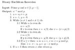
Thank you so much. Yes I got basic ideas of hardware oriented coding style.But i am not able to start coding like hardware. I am confused where to start an all. Can you give me an example of how to start it by writing code for this binary euclidean algorithm. FYI i have attached the algorithm here Untitled.jpg
 

But i am not able to start coding like hardware. I am confused where to start an all.
In that case you should start something simple and not complex.
Start with Verilog code for an up-down counter or a simple FSM (don't copy from somewhere, write your own code).
 

Status
Not open for further replies.

Part and Inventory Search

Welcome to EDABoard.com

Sponsor

Back
Top