Continue to Site

Welcome to EDAboard.com

Welcome to our site! EDAboard.com is an international Electronics Discussion Forum focused on EDA software, circuits, schematics, books, theory, papers, asic, pld, 8051, DSP, Network, RF, Analog Design, PCB, Service Manuals... and a whole lot more! To participate you need to register. Registration is free. Click here to register now.

VFD to control 3 phase AC induction motor 400V 6000 rpm

Status
Not open for further replies.
You are right sir. I think midnight 2:30 me jumped to result. I woke up and read my post and you are right. I ment to say "when motor torque is too low to move the load, it gets in to braking region and draws too much current".

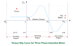
Full graph of Figure 1 in that pdf is like the one I attached. That graph is not representing the current situtaion. To get that graph you need to excite rotor externally to get in to generator region. At this point I guess we need to see a namogram including torque-current-speed when the machine is completely in motor region with a load and driven over synchronous speed.

I didn't wanted to put formulas for losses because I believe most of the losses are mechanical at this point (like in bearings) which I'm not an expert with. Experts suggests improving cooling for faster motor speeds.

But to speak about losses (copper and brush losses not mentioned)
Hysteresis losses are Pb = η * Bmaxn * f * V and eddy currents are related with frequency Pe = Ke * Bmax^2 * f^2 * t^2 * V
 

Attachments

  • 1456578362.gif
    1456578362.gif
    16.8 KB · Views: 106

Hello, Is not it easier for arduino to generate 3 SPWM signals instead of 6? These drivers have built-in dead time? Would that be a better solution than the smith trigger option?
Absolutely. The analog dead time generation was suggested according to your original single driver choice. I didn't study the Atmel code using 6 pwm outputs, but I doubt that it's safe in all circumstances.
 
Hello, Is not it easier for arduino to generate 3 SPWM signals instead of 6? These drivers have built-in dead time? Would that be a better solution than the smith trigger option?

Software solutions are inherently more flexible when compared to hardware solutions. It is rather easy to introduce dead-time in software. You need to invest some time in debugging though.
 
Hi,

Software solutions are inherently more flexible when compared to hardware solutions. It is rather easy to introduce dead-time in software. You need to invest some time in debugging though.
I agree: software is more flexible.

But here I don't see the need for flexibility. Dead time just needs to be large enough to prevent cross conduction.
Any further adjustment is not necessary.
The benefit with hardware is, that it is precise and doesn't suffer from processing power problems and other software relatedproblems with unexpected interrupts or resets.
For an H-bridge I prefer the hardware solution. But it's personal taste...

Klaus
 
Absolutely. The analog dead time generation was suggested according to your original single driver choice. I didn't study the Atmel code using 6 pwm outputs, but I doubt that it's safe in all circumstances.

Software solutions are inherently more flexible when compared to hardware solutions. It is rather easy to introduce dead-time in software. You need to invest some time in debugging though.

Hi,


I agree: software is more flexible.

But here I don't see the need for flexibility. Dead time just needs to be large enough to prevent cross conduction.
Any further adjustment is not necessary.
The benefit with hardware is, that it is precise and doesn't suffer from processing power problems and other software relatedproblems with unexpected interrupts or resets.
For an H-bridge I prefer the hardware solution. But it's personal taste...

Klaus

Hello,
Following your indications, I've decided to use this driver for my diy VFD: driversi.jpg
Please help me with the following issues:
1.What form should have the PWM signal from pins 3,4 and 5 CONN_01X07 to power the 3-phase SINUSOIDAL motor?
2. If the temperature read by the NTC sensor located on the IGBT FS100R12PT4 module (PIN 19,20) is higher than the one set in the software, the microcontroller puts the disable pin on high and the drivers stop?
ntcigbtbridge.jpg
3. Can anyone come up with a complete code? https://github.com/catphish/vfd

Thank you
 
Last edited:

Connect a rudimentary low pass filter (3 sets) to the pins 3,4 and 5.

it should be simple but must be able to handle the load power with some margin.

How does the IGBT module know about the temp set in software? You need to see the datasheet for a change!
 

Connect a rudimentary low pass filter (3 sets) to the pins 3,4 and 5.

it should be simple but must be able to handle the load power with some margin.

How does the IGBT module know about the temp set in software? You need to see the datasheet for a change!

The IGBT module incorporates a NTC temperature sensor. This sensor should be read by arduino and if the temperature rises above the one set in the code to put the pin 6 on the high and thus stop the drivers.
Everyone says it's simple but no one is willing to help me with this code.
This is my code but here only the frequency is adjustable - the amplitude is constant:


Code C# - [expand]
1
2
3
4
5
6
7
8
9
10
11
12
13
14
15
16
17
18
19
20
21
22
23
24
25
26
27
28
29
30
31
32
33
34
35
36
37
38
39
40
41
42
43
44
45
46
47
48
49
50
51
52
53
54
55
56
57
58
59
60
61
62
63
64
65
66
67
68
69
70
71
72
73
74
75
76
77
78
79
80
81
82
83
84
85
86
87
88
89
90
91
92
93
94
95
96
97
98
99
100
101
102
103
104
105
106
107
108
109
110
111
112
113
114
115
116
117
118
119
120
121
122
123
124
125
126
127
128
129
130
/******************************************************************
 * DDS-sinewave - 3phase
 *
 ******************************************************************/
#include "avr/pgmspace.h"
#include "avr/io.h"
// table of 256 sine values / one sine period / stored in flash memory
const unsigned char sine256[] PROGMEM  =
{
127,130,133,136,139,143,146,149,152,155,158,161,164,167,170,173,176,178,181,184,187,190,192,195,198,200,203,205,208,2,
10,212,215,217,219,221,223,225,227,229,231,233,234,236,238,239,240,242,243,244,245,247,248,249,249,250,251,252,252,25,
3,253,253,254,254,254,254,254,254,254,253,253,253,252,252,251,250,249,249,248,247,245,244,243,242,240,239,238,236,234
,233,231,229,227,225,223,221,219,217,215,212,210,208,205,203,200,198,195,192,190,187,184,181,178,176,173,170,167,164,
161,158,155,152,149,146,143,139,136,133,130,127,124,121,118,115,111,108,105,102,99,96,93,90,87,84,81,78,76,73,70,67,64,
62,59,56,54,51,49,46,44,42,39,37,35,33,31,29,27,25,23,21,20,18,16,15,14,12,11,10,9,7,6,5,5,4,3,2,2,1,1,1,0,0,0,0,0,0,0,1,1,1,2,
2,3,4,5,5,6,7,9,10,11,12,14,15,16,18,20,21,23,25,27,29,31,33,35,37,39,42,44,46,49,51,54,56,59,62,64,67,70,73,76,78,81,84,87,
90,93,96,99,102,105,108,111,115,118,121,124
};
#define cbi(sfr, bit) (_SFR_BYTE(sfr) &= ~_BV(bit))
#define sbi(sfr, bit) (_SFR_BYTE(sfr) |= _BV(bit))
#define PWM_OUT_1 11 // PWM output on pin 11
#define PWM_OUT_2 10 // PWM output on pin 10
#define PWM_OUT_3 9 // PWM output on pin 9
#define LED_PIN 13 // LED status on pin 13
#define TEST_PIN 7 // Scope trigger on pin 7
#define POTEN_IN 0 // Potentiometer on pin 0
#define OFFSET_1 85 // Offset for second-phase
#define OFFSET_2 170 // Offset for third-phase
double dfreq;
const double refclk = 31376.6; // measured
const uint64_t twoTo32 = pow(2, 32); // compute value at startup and use as constant
// variables used inside interrupt service declared as voilatile
volatile uint8_t icnt; // var inside interrupt
volatile uint8_t icnt1; // var inside interrupt
volatile uint8_t c4ms; // counter incremented every 4ms
volatile uint32_t phase_accum; // pahse accumulator
volatile uint32_t tword_m; // dds tuning word m
//******************************************************************
void setup()
{
 pinMode(LED_PIN, OUTPUT); // sets the digital pin as output
 Serial.begin(115200); // connect to the serial port
 Serial.println("DDS Test"); 
 
 pinMode(TEST_PIN, OUTPUT); // sets the digital pin as output
 pinMode(PWM_OUT_1, OUTPUT); // PWM output / frequency output
 pinMode(PWM_OUT_2, OUTPUT); // PWM output / frequency output
 pinMode(PWM_OUT_3, OUTPUT); // PWM output / frequency output
 // Setup the timers
 
 
 setup_timer1();
 setup_timer2();
 // disable interrupts to avoid timing distortion
 cbi (TIMSK0, TOIE0); // disable Timer0 !!! delay() is now not available
 sbi (TIMSK2, TOIE2); // enable Timer2 Interrupt
 dfreq = 1000.0; // initial output frequency = 1000.0 Hz
 tword_m = twoTo32 * dfreq / refclk; // calulate DDS new tuning word
}
//******************************************************************
void loop()
{
 if (c4ms > 250) // timer / wait for a full second
 {
 c4ms = 0;
 dfreq = analogRead(POTEN_IN); // read Poti on analog pin 0 to adjust output frequency from 0..1023 Hz
 cbi (TIMSK2, TOIE2); // disble Timer2 Interrupt
 tword_m = twoTo32 * dfreq / refclk; // calulate DDS new tuning word
 sbi (TIMSK2, TOIE2); // enable Timer2 Interrupt
 Serial.print(dfreq);
 Serial.print(" ");
 Serial.println(tword_m);
 }
}
//******************************************************************
// timer1 setup
// set prscaler to 1, PWM mode to phase correct PWM, 16000000/512 = 31.25kHz clock
void setup_timer1(void)
{
 // Timer1 Clock Prescaler to : 1
 sbi (TCCR1B, CS10);
 cbi (TCCR1B, CS11);
 cbi (TCCR1B, CS12);
 // Timer0 PWM Mode set to Phase Correct PWM
 cbi (TCCR1A, COM1A0); // clear Compare Match
 sbi (TCCR1A, COM1A1);
 cbi (TCCR1A, COM1B0); // clear Compare Match
 sbi (TCCR1A, COM1B1);
 sbi (TCCR1A, WGM10); // Mode 1 / Phase Correct PWM
 cbi (TCCR1A, WGM11);
 cbi (TCCR1B, WGM12);
 cbi (TCCR1B, WGM13);
} 
 
//******************************************************************
// timer2 setup
// set prscaler to 1, PWM mode to phase correct PWM, 16000000/512 = 31.25kHz clock
void setup_timer2(void)
{
 // Timer2 Clock Prescaler to : 1
 sbi (TCCR2B, CS20);
 cbi (TCCR2B, CS21);
 cbi (TCCR2B, CS22);
 // Timer2 PWM Mode set to Phase Correct PWM
 cbi (TCCR2A, COM2A0); // clear Compare Match
 sbi (TCCR2A, COM2A1);
 sbi (TCCR2A, WGM20); // Mode 1 / Phase Correct PWM
 cbi (TCCR2A, WGM21);
 cbi (TCCR2B, WGM22);
}
//******************************************************************
// Timer2 Interrupt Service at 31.25kHz = 32us
// this is the timebase REFCLOCK for the DDS generator
// FOUT = (M (REFCLK)) / (2 exp 32)
// runtime : 8 microseconds ( inclusive push and pop)
ISR(TIMER2_OVF_vect)
{
 sbi(PORTD, TEST_PIN); // Test / set PORTD,TEST_PIN high to observe timing with a oscope
 phase_accum += tword_m; // soft DDS, phase accu with 32 bits
 icnt = phase_accum >> 24; // use upper 8 bits for phase accu as frequency information
 OCR2A = pgm_read_byte_near(sine256 + icnt); // read value fron ROM sine table and send to PWM DAC
 OCR1A = pgm_read_byte_near(sine256 + (uint8_t)(icnt + OFFSET_1));
 OCR1B = pgm_read_byte_near(sine256 + (uint8_t)(icnt + OFFSET_2));
 if (icnt1++ == 125) // increment variable c4ms every 4 milliseconds
 {
 c4ms++;
 icnt1 = 0;
 }
 cbi(PORTD, TEST_PIN); // reset PORTD,TEST_PIN
}


I need the frequency and amplitude of the signal to be adjusted simultaneously up to 50 Hz.
Over 50HZ I need to adjust only the operating frequency and its amplitude stay constant at maximum value.
 
Last edited by a moderator:

I need the frequency and amplitude of the signal to be adjusted simultaneously up to 50 Hz.

I do not see that in the posted code. You need to clearly comment the software.

You need to have code for the startup (the motor may need special attention when starting!!)... I cannot find that...

Where does the software read the temp of the IGBT module?

Does the code compile OK? Does it run without problem?
 

I need the frequency and amplitude of the signal to be adjusted simultaneously up to 50 Hz.
The IGBT module incorporates a NTC temperature sensor. This sensor should be read by arduino and if the temperature rises above the one set in the code to put the pin 6 on the high and thus stop the drivers.
Where does the software read the temp of the IGBT module?
Hello,Tthe code does not contain these functions - I ask you to implement these functions in code if you know how to do this.


You need to have code for the startup (the motor may need special attention when starting!!)... I cannot find that...
As I said above, this code generates 3 sinewaves with variable frequency and only that.


Does the code compile OK? Does it run without problem?
The code compiles without errors just that to work well at frequencies below 50Hz needs the improvements that I mentioned above.
In order to function properly and to provide added safety, the code needs the following improvements:
1. Frequency and amplitude of the signal must be able to vary simultaneously from 0 to 50Hz and 0 to 5V. When the frequency goes above 50Hz the signal amplitude must remain constant 5V.
2. The IGBT module incorporates a NTC temperature sensor. This sensor should be read by arduino and if the temperature rises above the one set in the code to put the pin 6 on the high and thus stop the drivers

If anyone knows how to do it, please post the solution here
 

1. Frequency and amplitude of the signal must be able to vary simultaneously from 0 to 50Hz and 0 to 5V. When the frequency goes above 50Hz the signal amplitude must remain constant 5V.

You need to provide meaningful ranges: for example, 0Hz is not meaningful. You can use, say 50Hz to 100Hz or 25Hz to 100Hz or 100Hz to 400Hz etc.

Varying both freq and amplitude independently is not meaningful: for example, you can give a frequency range of 25Hz to 100Hz and say that the potential (amplitude) will be linear from 1V to 5V from 25Hz to 50Hz and const at 5V from 50Hz to 100Hz. This information you need to provide.

It appears that pins 19 and 20 refer to the NTC output and that can be read by the arduino. Because this is essentially a variable resistor, you need to provide a const current source (select a very reasonable value) and read the voltage at one of the arduino's ADC pin. Use the supplied information and calculate the temp in the arduino (this may not be really needed as we only need to determine the set point only once during the startup.

By the way, what is the current frequency the sine wave is getting output? You need to set the pre scalars in arduino in the right fashion.

How the arduino is getting the input about the frequency or voltage? Are you providing a potentiometer? As I mentioned above, it is good to change only one- say the output sine wave frequency- that too SLOWLY!

Is the arduino has any display attached? (say one LCD module to tell the speed, voltage etc); writing to displays can take away significant resources.

Frequency and the pre-scalar relations are not linear: for simplicity, use a table look up (use a stepsize of 2Hz or 5Hz for example, depending on the range).

Make the software modular: you will find debugging much easier.
 

If anyone knows how to do it, please post the solution here

Your are using the three PWM built-in outputs. In PWM, you control the pulse height only indirectly. Your basic control will be the pulse width.

When you pass that through a LP filter, the output voltage will be proportional to the pulse width (because the height is more or less constant).

The peak of the sine wave will be dependent on the max number in the table value (254 in your case: but the sine curve is shifted by 128 so that negative numbers are avoided).

If you want to reduce the peak of the sine wave, you need to scale these numbers (you can set the right prescaler register in arduino).
 

Your are using the three PWM built-in outputs. In PWM, you control the pulse height only indirectly. Your basic control will be the pulse width.
I agree with you but as you can see in the attached movie, the amplitude of the PWM signal oscillates when I actuate the potentiometer and adjust the frequency.
The Blue signal is the arduino PWM output and the yellow signal is the same arduino PWM after low pass filter.
https://www.dropbox.com/s/qwir9gfulo8wclf/WhatsApp%20Video%202019-04-09%20at%2016.48.02%20%281%29.mp4?dl=0

When you pass that through a LP filter, the output voltage will be proportional to the pulse width (because the height is more or less constant).
As you can see in my movie the PWM signal decreases in amplitude when frequency increases - the sinusoidal filtered signal maintains its constant amplitude.

The peak of the sine wave will be dependent on the max number in the table value (254 in your case: but the sine curve is shifted by 128 so that negative numbers are avoided).
That's exactly what I want to do my code - you see the attached image
AMPLITUDE.JPG
So I want the PWM signal (blue signal) to change its amplitude according to the set frequency as in the attached picture

If you want to reduce the peak of the sine wave, you need to scale these numbers (you can set the right prescaler register in arduino).
If I knew how to do this I would not have asked for your help

Thank you
 

The Blue signal is the arduino PWM output and the yellow signal is the same arduino PWM after low pass filter....

But why the arduino PWM pulses are sitting on a sine curve? The base line should have been flat. Are you having some mains frequency pickup? Please check.

What is the cutoff for the LP filter? Some amplitude may be lost due to the filter (I am not sure but ho harm checking).

Just look for the LP output (sine wave) and check whether they are of const amplitude within the frequency range.

Just try this out: insert the code after you define sine256:

for (i =0; i<256;i++) sin256=sin256/2;

and verify that the output is reduced in amplitude by 1/2.

Then modify the lines 121,122 and 123 to see the same effects (undo the earlier change first)

If that works, you need to apply the scale from the potentiometer.
 

To change output voltage at the load, change amplitude of the fundamental going to the op amp. Notice the SPWM waveform remains the same amplitude. You don't need to attenuate it. It always needs to be sufficient voltage to drive the mosfets entirely On-Off.

SPWM demo changing amplitude of fundamental to opamp changes V to load).png

The sine wave input amplitude was gradually increased. Notice the op amp output has 5V amplitude. The waveforms start with about 50% duty cycle, then take on SPWM shape. As a check, output is sent through an LC low-pass filter to the load. The LC filter is able to shape the +-5v square-ish waves into sines of a greater peak voltage.
 

The LC filter is able to shape the +-5v square-ish waves into sines of a greater peak voltage. ...

If you see carefully, there is a phase shift between the two sine waves. I presume that it is due to the LC filter but could you please confirm? But there is no change in frequency: why the phase got shifted?
 

If you see carefully, there is a phase shift between the two sine waves. I presume that it is due to the LC filter but could you please confirm? But there is no change in frequency: why the phase got shifted?

Yes, the inductor introduces power factor error. Hence the capacitor needs to be added to provide power factor correction. (It has the additional purpose to smooth ripple.) The LC values were found by experimentation, so that coil current waveform coincides with voltage waveform coming from upstream.

The load waveform does not coincide with the waveform coming from upsteadm. The reason is because of the load and capacitor interacting.
 

Status
Not open for further replies.

Similar threads

Part and Inventory Search

Welcome to EDABoard.com

Sponsor

Back
Top