Continue to Site

Welcome to EDAboard.com

Welcome to our site! EDAboard.com is an international Electronics Discussion Forum focused on EDA software, circuits, schematics, books, theory, papers, asic, pld, 8051, DSP, Network, RF, Analog Design, PCB, Service Manuals... and a whole lot more! To participate you need to register. Registration is free. Click here to register now.

VFD to control 3 phase AC induction motor 400V 6000 rpm

Status
Not open for further replies.
Hi,

what else should we know???
How many modifications did you make! ... and you want us to rectify it ...

Klaus

I just want to spin this motor but the halfbridge get into short circuit.
I just want to know what I did wrong in my circuit
I want to make him spin for the start and then I will make all the improvements in the circuit.
This is my control circuit output ALow and Ahigh - halfbridge driver input signal halfbridge input signal.jpeg

- - - Updated - - -

Low and high side IGBTs activated simultameously...

I understand this - please check again my control circuit output signals
halfbridge input signal.jpeg
 

Here's the a simulation of the original circuit. The sine frequency is increased to 500 Hz for better display of the pwm pulses. The signal pattern is faulty in several regards which corresponds well to the admission in the project report, that the full design has never been tested due to lack of components.

The circuit needs redesign from the scratch.

pwm1.PNG
 
Here's the a simulation of the original circuit. The sine frequency is increased to 500 Hz for better display of the pwm pulses. The signal pattern is faulty in several regards which corresponds well to the admission in the project report, that the full design has never been tested due to lack of components.

The circuit needs redesign from the scratch.

View attachment 152027

Hello, Can you simulate the same circuit with LM339 comparator ? Thank you
 

The only way you can use H-bridges to generate 3-phase, is not to connect motor windings to one another.

(The delta formation usually connects loads. By using H-bridges it creates current flow and shoot-through between the H-bridges.)

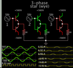
If you are willing to use a star formation, then use three half-bridges (one for each winding), and have a bipolar supply (+/- 560). Each winding is connected to ground at one end.

3-phase star bipolar supply +- 560v sine bias 3 loads 80ohm 1 grd 9mA.png

Notice that all loads receive the same amount of Amperes from their supplies during positive or negative cycle.
Notice that the ground is not absolutely necessary. My simulation has only 9mA at the ground. The supplies provide a return current path for each other.
 

The only way you can use H-bridges to generate 3-phase, is not to connect motor windings to one another.

(The delta formation usually connects loads. By using H-bridges it creates current flow and shoot-through between the H-bridges.)

If you are willing to use a star formation, then use three half-bridges (one for each winding), and have a bipolar supply (+/- 560). Each winding is connected to ground at one end.

View attachment 152029

Notice that all loads receive the same amount of Amperes from their supplies during positive or negative cycle.
Notice that the ground is not absolutely necessary. My simulation has only 9mA at the ground. The supplies provide a return current path for each other.

Hello, i want to use IGBT bridge to drive the motor : 8042711495740278292.gif
My half bridges go into short circuit without the motor connected. Thank you
 

Your schematic has all N-type devices. To shut off an N-device it needs to be biased at same voltage as the lower (more negative) terminal. Thus your low side needs bias voltage in the negative polarity, that is down to -560v. Does your control system provide that low voltage? If not then that explains why your half-bridges shoot through.

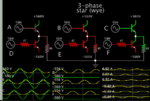
Simulation using all NPN bjt. Biasing was adjusted so the circuit performs properly. Notice the low side devices turn on when biased merely a few volts above -560v.

For the high side devices, using 0v bias voltage fails to shut them off. They need bias voltage far below 0v in order to shut off.

3-phase star bipolar supply +-560v 6 NPN sine +-bias 3 loads 80 ohm.png
 

Can you simulate the same circuit with LM339 comparator ?
Not necessary, behavior with LM339 is the same in this circuit, except for an additional delay of several µs caused by the LM358/LM324.

The circuit behavior can be predicted by analyzing it with pencil and paper. Your question suggests that you have difficulties to analyze the circuit, otherwise you won't ask.

Your schematic has all N-type devices. To shut off an N-device it needs to be biased at same voltage as the lower (more negative) terminal. Thus your low side needs bias voltage in the negative polarity, that is down to -560v. Does your control system provide that low voltage? If not then that explains why your half-bridges shoot through.

The OP uses state-of-the art-opto isolated IGBT gate drivers with correct supply as previously posted. The problem is not primarily in the power stage.

- - - Updated - - -

Hello, i want to use IGBT bridge to drive the motor : View attachment 152030
My half bridges go into short circuit without the motor connected. Thank you

In other words, you are asking for the correct switching pattern that has to be applied to the 6 iGBT.

I reviewed the project report where you got the control circuit from, unfortunately it involves a basic misunderstanding of VFD inverter operation. Consequently the circuit is designed based on this wrong concept.

For this particular case, we are interested in producing a PWM signal that will be produced by toggling a switch ON/OFF for the positive portion of a sin wave, and doing a similar operation to a separate switch for the negative portion of a sin wave.

Instead of two switches that are activated exclusively for positive and negative half wave, a half bridge driving reactive loads must activate the switches alternatingly (with a short dead time of a few 100 ns up to a µs). Thus the control circuit design with the blanking comparators (also the previously discussed rectifier model) is completely wrong for a motor inverter. The reported bridge short is an extra problem, one of the several design faults that the author has added on top of a basically wrong concept.

- - - Updated - - -

The schematic in post #45 brings a nice pwm waveform in the lower right corner. It makes sense to consider how this waveform that we usually call "three level pwm" can be achieved. Hint: it's not the output of a single half bridge, because the half bridge has no neutral switch. Just turning H and L switch off doesn't return the output to zero. Actually the three level waveform is the phase-to-phase voltage of the inverter.
 

Hi,

LM339 has open drain output, thus I´d add a pullup.

Klaus
 

Hi,

I referred to post#43 where the OP asks about LM339 simulation ... and the circuit in the same post doesn´t show a pullup..

But yes, other circuits show the pullup.

Klaus
 

O.K., I was referring to the original project circuit that was linked in post #29, see Page 31. I admit that I shouldn't make assumptions like "the OP surely knows that…". View attachment 152043

Hi,


One is a comparator, the other is an OPAMP. The both (sadly) use the same schematic symbol,
* but the OPAMP is designed for low differential input voltages and analog output
* but the COMPARATOR is designed for high differential input voltages and digital output

There are many other differences.

When you replace parts, then you should know why and how to replace them. The ouput signal will differ a lot. In timing in function and in signal levels. .... this is what I mean with "learning the theory first"

***
Your PCB is single layer without GND plane. Expect EMI/EMC problems and increased noise. A copper pour is no solid, low impedance GND plane.
The reference design uses 2 layers with GND plane. --> If you modify this, you should know why and how and waht are the risks.

***
The wiring is a mess. This is not how a "switching power" application needs to be wired. You need to take care about wire lengths, ground bounce, return paths.
Ground bounce is caused by high currents, high dI/dt, signal loop impedance...

***
Scope:
This is the smallest problem.

***
My recommendation: Read application notes from reliable sources. Many semiconductor manufacturers (IGBT, MOSFET, gate driver IC...) provide such documents.
They are for free, so use them. They provide this documents because they see the need for it. Even experienced electronics designers should read them when they enter the new filed of "power electronics". There´s a good reason for it.

*****
I see a lot of mistakes. No wonder the result is not what you expect.

Believe me, I would be gald if I coud tell you: "modify the value of resistor X and everything will work". But this isn´t the case.
Designing a 6kW VFD isn´t simple. It is complex. It is complex from the theory and from the hardware design. There are so much pitfalls...

Klaus

Hello, I asked if you can simulate with comparator LM339 because you say that a comparator differs from an OP Amp and because i found this:https://www.google.com/url?sa=t&rct=j&q=&esrc=s&source=web&cd=1&cad=rja&uact=8&ved=0CB0QFjAAahUKEwi8s8eUzrDIAhWH04AKHVz5A0c&url=http%3A%2F%2Fforums.parallax.com%2Fdiscussion%2Fdownload%2F96248%2Fop%2520amp%2520vs%2520comparators.pdf&usg=AFQjCNEMHK_P-4XpPHg6azYE5nmTe6vzKg&sig2=gZDPmgwFVqpYFpNHAqgTwA
 

I did already answered your question. The TI paper holds no relevant facts for the particular application. There's a clear convention how to assign inverting and non inverting input in the circuit symbol, the noninvering input is in phase with the output pin. You can look at the pin numbers and verify that LM339 is used in the project schematic according to this convention, in so far there are no open questions related to the usage of this part.

Harping on about the LM339 theme makes only sense if you assume that the project circuit is a trustworthy blueprint for your VFD design. Quite a bit careless.

- - - Updated - - -

It's generally correct to emphasize the differences between OP and comparator properties. But there's no problem to use an OP as slow comparator as in the present circuit.

As I told you earlier, I agree to follow your advice and change the command circuit. I would still keep the arduino and the low pass filter . Do you think you can help me with this? Do you think you can help me make a new command circuit based on arduino DDS and possibly another way to get the dead time required to operate this VFD?
Thank you
 

I don't see a useful purpose for the low-pass filter and comparator. H and L gate should be driven by the direct respectively inverted pwm signal, modified by a dead-time generator. I see the problem that Arduino isn't powerful enough to generate all 6 gate signals internally, including dead time.

I forgot to mention that 32 kHz is too fast for an IGBT power stage, better plan a frequency between 8 - 16 kHz.


Hello,
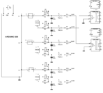
What do you think if I replace the comparators with nand gates and trigger smith gate driver? What do you think about this circuit? Isn't that gonna work? I mention that I want to make a VFD in the open loop without current sensors or hall sensors.
Thank you
inverter DDS.GIF
 

The circuit drives the inverter with square waves instead of sine pwm. You can have this much easier by sending square waves out of the micro controller, don't need the dds stuff.
 

My suggestion so that your work enviroment is safer when you test your motor with higher voltages.

Simply send your motor to a motor rewinder. Let him rewind your motor from 3 phase 400Vac to 3 phase 24Vac. It will not cost too much. The rewinder can use the same enamelled wire. It costs you maybe 50-60 USD.

After that you can test all your system including the IGBTS with 24VDC Bus.

After you test all the fuctionality, you raise your DC bus to 560VDC and change your motor windings back to 400Vac and make further enchancement.

This is a more safer way.
 

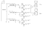
I would change the control circuit like this:

inverter mod.png

There should be a feature to disable the output stage (e.g. by AND gates).

For maximum output voltage, the 3-phase sine pwm should be modified by a zero sequence, see link in post #22. But without it, the inverter should be basically working. You also need to vary the sine magnitude according to V/f characteristic, not sure if this function is already in your code. Magnitude variation is not implemented in the posted project report.
 

I think it's far more beneficial if I solve this problem here - I think many of our children will have a lot to learn. So the benefit would be millions of times bigger than if I bought a VFD...

A very valid point indeed.

But the suggestion to buy a readymade one was made because of cost and time. Learning something new does take time and is not cheap. Also you should not try with a powerful motor in the beginning...

Two points that were missed in earlier posts: bearings will wear out twice as fast; the windings will have twice the mechanical stress (because of centrifugal force) when running at double the speed.

If you do not increase the voltage, the motor will deliver less than 1/2 the power (boilerplate) but if you start with a higher power motor, you will have starting problems (that is not seen the diagrams) that need to be attended to seriously.

In the lab, we have ultracentrifuge that can run upto 70k RPM; the earliest one I saw used a belt and pully and a regular motor.

Gas centrifuges run at 100k RPM but the driver is so complex (US put a virus in the software and 100s of these centrifuges crashed in Iran).

I am all for learning but we need to begin small; the Chinese units do work but the quality is barely acceptable. But that is their philosophy of design (and cost effective).
 
Status
Not open for further replies.

Similar threads

Part and Inventory Search

Welcome to EDABoard.com

Sponsor

Back
Top