Continue to Site

Welcome to EDAboard.com

Welcome to our site! EDAboard.com is an international Electronics Discussion Forum focused on EDA software, circuits, schematics, books, theory, papers, asic, pld, 8051, DSP, Network, RF, Analog Design, PCB, Service Manuals... and a whole lot more! To participate you need to register. Registration is free. Click here to register now.

RF Limiter not working as it should

Status
Not open for further replies.

syedhamzahasan

Newbie level 6
Joined
Jan 23, 2015
Messages
14
Helped
3
Reputation
6
Reaction score
3
Trophy points
3
Location
Islamabad, Pakistan
Activity points
129
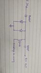
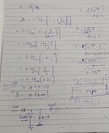
We have designed a RF limiter in 1.5MHz to 30MHz range with working power level of -40dbm and above. It should not operate in case of weaker signals from -40dbm (FYI our desired range is -120dbm to -50dbm) and start from here to stronger. The problem arising is that it is ON, on all power levels without biasing. Means we are giving it strong signal and the signal is still passing through the limiter. Diode used is MA4E2054. The circuit and calculations we used are also attached. If someone could help that would be great.
Thanks
 

Attachments

  • WhatsApp Image 2019-03-19 at 12.32.57 PM.jpeg
    WhatsApp Image 2019-03-19 at 12.32.57 PM.jpeg
    42.1 KB · Views: 123
  • WhatsApp Image 2019-03-19 at 12.34.55 PM.jpeg
    WhatsApp Image 2019-03-19 at 12.34.55 PM.jpeg
    114 KB · Views: 121
  • MA4E2054_Series.pdf
    753.6 KB · Views: 83
Last edited:

I would expect antiparallel diodes instead of two diodes with same polarity. What's your specification for the limiter (output versus input level, operation frequency)?
 

Use PIN switch diodes and it will work - that is, if you control the bias current from some sort of AGC.
 

What you mean with " without biasing" ? DC level was 0 V, or the inductor was disconnected ?
The inductor must be conected to ground directly or through a DC power supply, otherwise the DC voltage generated by the diode can't flow. Thus the circuit can't work.

Using an antiparallel diode, the DC current will flow through the directly ploarized diode (that depends from the polarity of the input waveform) so the inductor is no required and it will work as zero bias limiter. In this case the biasing could be a little bit more complicated
 

For one thing, diode based limiters usually trip on around, say, 100 milliwatts or so. Expecting one to turn on at -30 dBm is pure folly.
 

Status
Not open for further replies.

Part and Inventory Search

Welcome to EDABoard.com

Sponsor

Back
Top