Continue to Site

Welcome to EDAboard.com

Welcome to our site! EDAboard.com is an international Electronics Discussion Forum focused on EDA software, circuits, schematics, books, theory, papers, asic, pld, 8051, DSP, Network, RF, Analog Design, PCB, Service Manuals... and a whole lot more! To participate you need to register. Registration is free. Click here to register now.

BGAP circuit with op-amp

Status
Not open for further replies.

daniel442

Junior Member level 2
Joined
Dec 29, 2017
Messages
20
Helped
0
Reputation
0
Reaction score
0
Trophy points
1
Activity points
199
Hi all, I'm having troubles designing this circuit which supposed to be a BandGap circuit with op-amp topology (instead of current mirrors).
bgap_op_am.png
in theory, the op-amp supposed to force V2=Vd using a negative feedback. in simulation you can see that Vd is not equal to V2 (~70mV difference) and if I continue to simulate IR3,IR2 which supposed to be equal as well (I0 in theory) there is also some mismatch and off course V_ref is no const. over temperatures...
This circuit is rather simple in his theory and I think that the op-amp parameters are wrong. I've used it from ahdllib (which I am not really familiar with) and configure it as an ideal op-amp (high Rin, low Rout, high Gain).
appreciate any help.
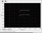
vd_v2_sim.png
 

The opamp output is sitting on the positive rail. It try to raise the top node voltage, but supply is not enough high. The ratio of the r1,r2 resistors are not good I think. r2 should be much smaller, or r1 should be bigger.
 

I think you want a lot more than a 1:2 ratio of transdiodes'
area. I like 8-16X on the big side. 2:1 doesn't give you much
"input signal" to work with. And then with the headroom
problem and the inevitable gain reduction when so-slammed
you can't close the loop.
 

regarding -
The opamp output is sitting on the positive rail. It try to raise the top node voltage, but supply is not enough high. The ratio of the r1,r2 resistors are not good I think.

what do you mean by sitting on the positive rail ? if V2 will increase the voltage (V_ref) through R3 will try to decrease V2 and not increase it. please explain.
R1 determine the nodes current and I have calculated it is sufficient enough (I=Vt*ln(N)\R1 where N- number of diodes in parallel). are my calculations wrong ?
I think you want a lot more than a 1:2 ratio of transdiodes'
area. I like 8-16X on the big side.

I have designed with the same technology, Vdd and number of diodes (2) the same BGAP circuit but with current mirror topology (attached) and didn't face any issues with voltage...
I do agree that designing with 8,16,32 diodes will decrease any mismatch but the BGAP circuit should work even with 2 diodes.

As I said, the only "new" thing I have used here is the opamp from ahdlib and I have "configured" it manually, can this be the issue here?
thanks
 

There are two things that can be wrong with your circuit:
1. Your loop is clearly not stable which is causing your output voltage to sit near Vdd (3.3V). The op-amp output cannot go any higher than this because that is your Vdd! Increasing Vdd will not help. Flip your op-amp and see if you get the correct voltage.
2. Your operating point for the output of the op-amp is higher than 3.3V in which if you increase Vdd it will help...

I also see your betadc ~ 2 which is quite low! Clearly your BJTs are not biased properly!
 

If you still have problems with the OPAmp you should try to add VCVS from analogLib.
 

Status
Not open for further replies.

Similar threads

Part and Inventory Search

Welcome to EDABoard.com

Sponsor

Back
Top