Continue to Site

Welcome to EDAboard.com

Welcome to our site! EDAboard.com is an international Electronics Discussion Forum focused on EDA software, circuits, schematics, books, theory, papers, asic, pld, 8051, DSP, Network, RF, Analog Design, PCB, Service Manuals... and a whole lot more! To participate you need to register. Registration is free. Click here to register now.

[SOLVED] Stability Simulation with Cadence

Status
Not open for further replies.
Exactly FvM that was the thing I mean, from the oscillation at the output in closed loop system after applying the step input signal indicate the stability. Thank you for your confirmation.

Could you please FvM suggest me a method of stabilizing my CMFB loop rather than reducing the CM gain,

Do you think if I move the VCMFB (or the Vcms) control voltage to the upper mirror of the cascode amplifier (vbias7 in my circuit image) will have better stability than my current one (now I am controlling the down mirror of the cascod stage).

I am again posting my circuit to easy referring to it

fully diff.jpg

Thank you once again
 

For sure those two characteristics of the feedback system (step response of the input and step inside the loop) are related. And yes, by stepping the input we can see if the system oscillates. My only purpose when advising for injecting a disturbance inside the loop was to see how the loop corrects for that and how it does it.

Junus, it will be difficult to come with a compensation strategy online. But it looks to me it won't be as easy as just placing caps to ground here and there. You have 3 stages in your CMFB loop - the first stage, the second stage and your error amplifier.

- - - Updated - - -

Also, don't forget the local feedback loops of the cascode compensation (I think we discussed that some time back). Have you tried placing caps in parallel with each of your output common mode sensing resistors? This will create a zero in the CMFB loop.

Since you're simulating with iprobe, you get the overall loop gain as a result. A good way to debug these loops will be to go to the old way of simulating ac stability. For example, break the loop between the inverting input of your error amplifier and the middle point of the common mode sensing resistors. You break it by placing a huge inductor in series - 1 to 10H. It will keep the loop closed for DC but will break it starting from some very low frequency. At that break point, on the side of the error amplifier inverting input connect a big capacitor (for ex. 1F) in series with your test ac voltage source (dc =0 and ac=1), the other side of that voltage source connected to ground. Run ac (not stb) simulation. At least for low frequencies you should see the same loop gain as with iprobe. For high frequencies there will be differences and also now you'll have a resonance peak at some low frequency (hopefully very low) from the big L and C. With this setup you disturb the loading of the loop at the break point but if it happens at sufficiently high frequency, you'll still be able to debug at lower frequencies.
Now, this setup allows you to find the transfer function between any two points around the loop and see where the troubles come from. For example you can look at the transfer function from the input of the error amplifier to its output. Then you can look from the output of the error amplifier to the output of the 1st stage of the main amplifier and so on.
 

Dear Suta,

I thank you very deeply for your kind and very useful explanation, you pointed me to one important concept that my loop consist of three stage amplifier which for sure not easy to compensate. I will try your suggestion of connecting the inductor once I reach the lab,

Concerning the parallel capacitors across the average common mode resistors, I have already connected it with value of 150 fF across each, I would say it improved the stability but not that much, however I am keeping it.

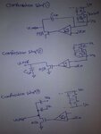
Dear FvM, thank you very much for your suggestion, indeed you reminded me that I have done a mistake, in my first way to compensate the loop, I connected the miller capacitor at the output of M3 of the Common mode amplifier, but as you said it must be at the output of the M3A since my actual VCMFB is ending here, so I will try this as well tomorrow and I will inform you about the result, there is also other two scheme I will correct according to miller compensation and I showed he below..

Only I wonder if this capacitors will effect my slew rate of the differential mode amplifier or not ?

Thank you once again my mentor.

compensation.jpg
 

*****************************************Update***************************************

The origin of the problem of the stability in my CMFB loop is coming from the reason that my CMFB loop bandwidth is actually higher than the bandwidth of the differential mode gain, hence definitely the poles of the differential mose will appear in the CMFB loop and degrade severely the phase margin.

In my attempt to reduce the gain by reducing the differential transistors of the CMFB amplifier, the loop is becoming stable not because of reducing the gain of the error amplifier but due to the reduction of the GBW of the CMFB as consequence of this change,

Now we have two options for reducing the CMFB bandwidth loop
1. by reducing the input transconductance of the error amplifier: drawback is reduction in the loop gain accuracy
2. by using the miller capacitors : the scheme which I am going to use

Source of this information [Allen holberg, Gray]
 

I'm a bit confused. Does your M3A correspond to Q37 in your amplifier schematic?
Correct me if I'm wrong but I think you connect the middle point of your CM averaging resistors to the inverting input of the CM error amplifier. If so, then you are connecting a miller cap across two inverting stages as in setup1 and 3 and this is definitely not correct.
 
Dear friends,
seems I reached the end of this post,

I tried all the types of compensation my common mode feedback loop but non is working, now I have a phase margin of 45 which I gonna accept,

Thank you very much for you assistance
 

dear friend:

What your said is helpful for me, and could you share the article (that comes form frank as you mentioned ) with me, I am confused with fully differential opamp's STB analysis.

thank you very much!
 

Status
Not open for further replies.

Part and Inventory Search

Welcome to EDABoard.com

Sponsor

Back
Top