Continue to Site

Welcome to EDAboard.com

Welcome to our site! EDAboard.com is an international Electronics Discussion Forum focused on EDA software, circuits, schematics, books, theory, papers, asic, pld, 8051, DSP, Network, RF, Analog Design, PCB, Service Manuals... and a whole lot more! To participate you need to register. Registration is free. Click here to register now.

High ampere DC motor FET Bridge Driver

Status
Not open for further replies.

fawadbutt

Member level 3
Joined
Oct 29, 2010
Messages
61
Helped
4
Reputation
8
Reaction score
4
Trophy points
1,288
Location
Lahore, Pakistan, Pakistan
Activity points
1,754
ir2101-motor-driver-hbridge-irfz44n-mosfet.png i m using this circuit and trying to Drive DC motor , i generate 61 Khz PWM frequency for speed controlling . bootstrap capacitor i use is 1uf.
but when motor ran farword speed change but in above 50% pwm circuit short, when run revers no shortage but speed not vari , and on 1 ampare load fet(75n75) getting hot.
suggest me one more thing for fet driving which one is better ir2104 or ir2110 ..?
 

Hi,

Don´t blame it on the IR21xx drivers. They are not the problem.

The problem most probably is not in the shown circuit.

I rather think the problem is:
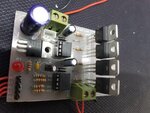
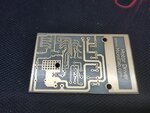
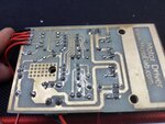
* in the PCB layout --> show us your PCB layout
* the driving signals --> show us a scope picture of the driving signals
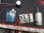
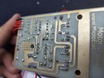
* the wiring, especially GND wiring. --> show us a photo of the wiring
* soldering problems, unsuitable parts --> show us detailed photos of your circuit

Klaus
 

Hi,

designing a PCB layout is not just connecting the pins of devices.
In short: With this PCB layout you won´t get it working reliably.

You need to learn a lot.
For now I recommend to go to the Infineon internet site, go to IR2101 page, and go through all the Application note.
(This you should do with all the devices you use now and in future. There is a good reason why they provide all this documents.)

If you had a look at all the numerous "IR21xx discussions" .. you will always read the same: You have to take care about the current paths, to be low impedance.

Many nowadays applications simply are not useful to be routed as single layer PCB. And especially with your "high current high speed switching application".
A trace is not an ideal connection anymore - it more and more (with increasing current and increasing signal rise/fall rate) becomes an inductor...causing voltage drop and oscillations.

More details you will find in the said application notes and the already existing discussions.

Klaus
 

i m in testion phase and my load current is 1 amp , when i use high current load then i use havy track and wire.
problem is fet getting hot on samll amount of current and behave different in both direction with same freq and pwm.
i think my bootstrap cap value is wrong.
what is the best value on 16 to 20 Khz switching frequency.
 

You did not understand,

It is not the absolute DC current level, it is dI/dt.
 

Status
Not open for further replies.

Similar threads

Part and Inventory Search

Welcome to EDABoard.com

Sponsor

Back
Top