Continue to Site

Welcome to EDAboard.com

Welcome to our site! EDAboard.com is an international Electronics Discussion Forum focused on EDA software, circuits, schematics, books, theory, papers, asic, pld, 8051, DSP, Network, RF, Analog Design, PCB, Service Manuals... and a whole lot more! To participate you need to register. Registration is free. Click here to register now.

Water level sensor circuit for wireless monitoring

Status
Not open for further replies.

kavin_eees

Member level 3
Joined
May 11, 2012
Messages
57
Helped
2
Reputation
4
Reaction score
2
Trophy points
1,288
Activity points
1,842
Dear all
Right now am involved in a project called wireless water level controlling / monitoring system..

previously i designed wired water level controller its works good...

but now planned to design wireless using low power RF

one transceiver in tank and one in the motor side. The transceiver in the tank side is to be operated by a two duracell battery...

now am in need help in designing low power water level sensing circuit using battery..

thanks in advance!!!
 

Re: water level sensor circuit for wireless monitoring

Hi,

You know what they say - Ask a vague question, get a useless answer... ;) Low power: 1mA or 1nA per day or per year? Is it in a dark enclosure? It it for 1,000,000 litres or 50ml? etc.

Anyway, the bulk of the current drawn is supplying the TLV431 with ~800uA. A reference with a lower supply current would be an idea, such as a resistive divider (but that would create a falling ref wrt battery voltage). The actual sensing circuit, which as you can see is just a variation on a very, very standard premise/design (the so-called "lie detector" aka "soil humidity sensor" aka "water level sensor" open or closed path to gnd or wherever the designer fancies), in simulations draws approximately 130uA to 170uA at 3V and will certainly work down to around 2.4V or lower. You could even dispense with the comparator, frankly but then have to spend time designing in battery voltage drop and ensuring Vbe and/or VOH is still attainable.

water level detector.JPG

I'm interested in seeing serious suggestions for a low power water level sensing circuit.

- - - Updated - - -

Hi,

I'd thought of pressure sensor water level detecting too because I'd thought about avoiding corroding wires and so on, but at first glance it looks as though it is more complicated parts-wise and calculations-wise than a simple yes/no circuit really requires. e.g. Liquid-Level Monitoring Using a Pressure Sensor

I simulated the above comparator circuit using a diode-connected NPN as the reference (instead of the TLV431) and it does use far less quiescent/housekeeping current and seemingly functions from 0º to 100ºC. Not sure I'd want to chance that sort of temperature-dependent reference unless I'd done some real testing first.

Far more economical re quiescent current is the bjt trio seen in so many of these circuits. Looking at what I was simulating, I think it's better to have the output go low when the water level drops below whatever level as that way the bulk of the current is drawn then and not all the time just to let the user know that there is water above x level. As you appear to be using a PIC/MCU that's not an issue I guess as input levels and what they signify can be defined in the code. Two more simulation screenshots for comparison of this idea about minimising current draw with active high or active low signals:

water level detector bjts low power.JPG

water level detector bjts not low power.JPG
 

Re: water level sensor circuit for wireless monitoring

Hi,

Well, evidently we can. There are a variety of capacitative moisture (soil humidity) sensors out there. Nice document you link to, a ready-made solution for you perhaps.

I didn't know pure water is 20MOhms/cm3, tap water is ~2k5, "dirty" river water is maybe 200R, and seawater is ~30R... No wonder people add salt water to earth test points before getting their Megger results :).
 

Re: water level sensor circuit for wireless monitoring

hi d123

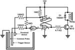
can we use the following circuit... i think it be easy....

water-sensor-circuit-schematic-trigger-diy-enthusiasts-wiring.jpg
 

Re: water level sensor circuit for wireless monitoring

Hi,

I don't know. It looks like a SR latch. May or may not be particularly reliable. You'd need to simulate and/or breadboard it to see how reliable its operation is. What does "two duracell battery" mean regarding supply voltage?
 

Re: water level sensor circuit for wireless monitoring

It is an SR latch and it should work with some caveats:

1. The water container must be electrically isolated, no other electrical connections (via metal pipes etc.) are allowed unless they are bonded to the "Common Probe".
2. The ICs must be CMOS types (CD4000 series for example).
3. There is a roughly 50% chance of the relay operating if the circuit is powered up when the tank is empty or above threshold level.

As mentioned earlier, the circuit relies on electrical conduction through the water so its resistance must be fairly low. That largely depends on dissolved salts and it may not work at all if for example distilled water is used.

Brian.
 

Re: water level sensor circuit for wireless monitoring

Industry standard level control relays for electrodes have adjustable threshold range, e.g. 1k - 100k resistance. It's suitable for drinking water, but not for deionized water. The latter can use e.g. high frequent capacitive sensors. Level sensors shouldn't use DC voltage which causes electrolysis and electrode corrosion.
 

Re: water level sensor circuit for wireless monitoring

Hi,

Further to previous comments, particularly FvM's regarding not using DC voltage, maybe a quadrature oscillator (or Wien-bridge oscillator) could be used to transmit a signal across the electrodes which could either just have the peak sensed or be rectified and monitor that voltage presence or absence.

Without solid information about voltages, actual battery type, what "low power" means to you in numbers, and what the circuit specifically has to do (sense absence/presence or sense two levels? etc.), Kavin, it's relatively pointless contributing to this "how long is a piece of string"/"guess what the specs are" thread much further, to be honest with you...
 

Re: water level sensor circuit for wireless monitoring

The technique I use on a commercial product I designed uses a PIC MCU. It alternately drives two probes which have a 100nF capacitor between them. Several ADC samples are taken from the un-driven probe to read the rate of discharge of the capacitor as the polarity across it reverses. Any residual resistance from either probe to the other probe or to any other object unbalances the shape of the discharge curve and triggers an alarm. Electrically it is extremely simple and the average voltage across the probes is always zero. It takes a little software to check the ADC readings but it does not suffer electrolytic corrosion and it triggers when the resistance between the probes is anything less than about 1M Ohms. The capacitor makes it relatively immune to AC pickup and EMC.

Brian.
 

Re: water level sensor circuit for wireless monitoring

hi all
thanks for your reply
previously we designed wired level indicator which uses 12v ac signal for sensing the water level..

*now we are trying to design wireless sensing using cc1101 module and the pic16 micro controller . the battery may be two 1.5v or 9v duracell battery...
*our aim is to design the circuit for long lasting with the above said battery specifications.
* we have to measure two levels in the tank (lower level and high level)
* any ideas for sensing circuit will be most helpful for us..
*we will uploaded our previous 12v ac circuit here.
View attachment 12v ckt.jpg
 
Last edited:

Re: water level sensor circuit for wireless monitoring

Hi,

low power:
* use a solar cell
* maybe a measurement every 5 minutes is sufficient --> set all circuit to "sleep" in the meantime.
* I recommend to rather use 2 x AA cells than a 9V block.

Klaus
 

Re: water level sensor circuit for wireless monitoring

hello,

suggestions :

cold point of 12V transformer must be connected to ground
Resistor between E C transistor to confirm the level 1
MCU links ! pull up + 0V
capacitor in AC polyester or 2 electrochimiques
additional load 1K on negatve alternance , instead of short circuit

water_level_sensor.jpg
 

Hi Kavin,

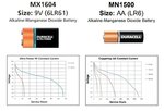
Not adding a circuit or much of use here, just a battery comment - I agree with Klaus, in case you are not aware of this (which I doubt), 9V batteries drain much faster than 1.5V:

Duracell 1_5V and 9V comparison of discharge curves.jpg

As the PIC can operate at 1.8V, if I'm not mistaken, you'd need two AAs in series - shame as two in parallel would have extended battery life by double the time/current draw.

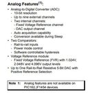
Also, does the PIC have the analog section or not?

PIC16LF1454 analog specs.JPG

I ask as it has - for example - a 1V reference and two comparators, very useful.

It seems the best offer on the table so far by a long shot is Brian's description of the device he designed, it seems to match your needs very well so I guess "reverse engineering" his product might be the way to go ;).

Links to PIC16(L)F1454/5/9 datasheet, Duracell Ultra Power 6LR61 9V and Duracell CopperTop MN1500 LR6, just so we all know what precisely is being referred to.
 
Last edited:

hi d123
thanks for your words....

dear brian
if possible you can share your ideas and circuit for sensing only...
it could be helpful for us in developing...
 

Of course I would have to kill you for reverse engineering one of my products. :fight:

The principle is quite simple though:
1. decide on a PIC with at least two ADC input pins. Lets call them A and B.
2. add a resistor from each of the pins to ground (VSS). I also add some voltage protection, work out what will appear on the ADC inputs!
3. add a ceramic non-polarized capacitor across the two probes - at the probe end of the wiring.
4. Drive A high as a digital output while reading B in as an analog input.
5. Take two readings of the voltage on B spaced slightly apart. (within the charging 'spike' time of the capacitor).
6. Drive B high as a digital output while reading A in as an analog input.
7. Take two readings of the voltage on A spaced slightly apart (same timings as step 5).
8. Do some math on the four readings to see if any leakage occurred. This would indicate there is conduction between the probes.
9. Go back to step 4.

So instead of measuring DC conduction, it measures the RC charge/discharge slope between the probes. The voltage across the probes reverses at each measurement so the net voltage is zero. It can also detect broken probe wiring (capacitor not seen) and to some degree, changes in capacitance across the probes even when there is no DC current path. It is fairly immune to LF pick-up from AC mains equipment. Works with water, oil and with a caution given to the user, with inflamable fuel levels too. Maximum probe voltage to ground or between probes never exceeds 3V and the current is limited to about 1mA. Note there are only two probe wires yet it can detect if one or both is broken, even with nothing additional linking them together.

Brian.
 

dear brian
here with i had attached the contact type sensor which we are planned to use...
**broken link removed**

you told to add capacitor at the end of the sensor right? if so its not possible to add at the end.
or can we add at the beginning?

- - - Updated - - -

hi d123
i agree with your points.
we can use 2 nos of AA batteries...
 
Last edited:

I can't open your attachment but it may be due to slow internet at my end - getting a massive 20K download speed today :x

The capacitor technique I mentioned is only applicable in my design, it relies on the capacitor and its placement at the probe end to work properly. Your designs may work differently and a capacitor might be detrimental to operation.

Brian.
 

hi brian

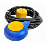
can we use cable float , if so it will be so easy for sensing

cable-float-switch-500x500.jpg
 

Which Wireless modules you are using? Radio Frequency, bluetooth or wifi etc which one ??
And also tell me at both ends which PIC microcontroller is being used or using 1 PIC and Encoder and decoder IC.
And also model of water level sensor
 

Status
Not open for further replies.

Similar threads

Part and Inventory Search

Welcome to EDABoard.com

Sponsor

Back
Top